
Cyclone separator with surface vanes

a surface vanes and separator technology, applied in the field of cyclone separators, can solve the problems of stagnation level, excessive re-entrainment of dust particles back, and current design practices that do not optimize the combination of axial and tangential velocities, etc., to achieve the effect of reducing axial flow rate, increasing pitch angle, and flattening pitch

Inactive Publication Date: 2005-01-04
CECO ENVIRONMENTAL IP INC
View PDF12 Cites 40 Cited by
  • Summary
  • Abstract
  • Description
  • Claims
  • Application Information

AI Technical Summary

Benefits of technology

The present invention provides vanes in the inside conical wall of the cyclone separator in order to control the axial velocity of the gas flow stream in the cyclone separator. In a preferred embodiment, the angle of the vanes is adjustable. Thus, if the pitch of the gas flow into the cyclone is too steep and the axial flow is too high, the vanes may be adjusted to a shallow angle to flatten the pitch and reduce the axial flow rate. On the other hand, if the pitch of the gas flow is too shallow and the axial flow is too low, the vanes may be adjusted to a more pronounced angle to increase the pitch angle and increase the axial flow rate.

Problems solved by technology

Current design practices do not optimize the combination of axial and tangential velocities of the gas flow in the cyclone separator.
This results in a stagnation level in some cyclone cones, and in excessive re-entrainment of the dust particles back into the effluent gas flow stream in other cases.

Method used


Image

  • Cyclone separator with surface vanes
  • Cyclone separator with surface vanes
  • Cyclone separator with surface vanes

Examples


Embodiment Construction

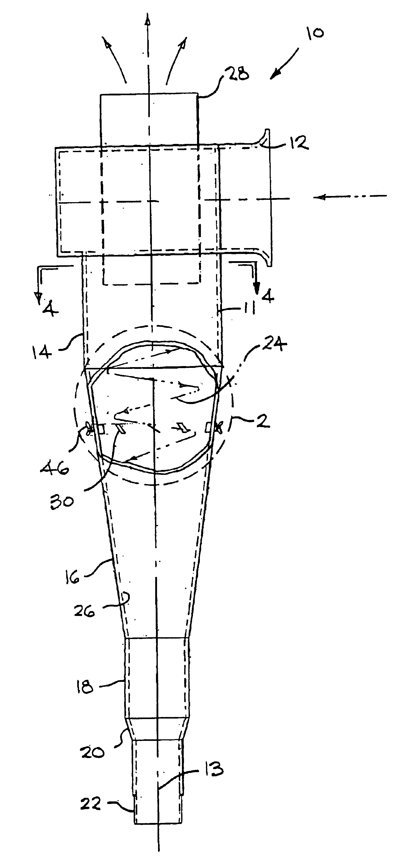
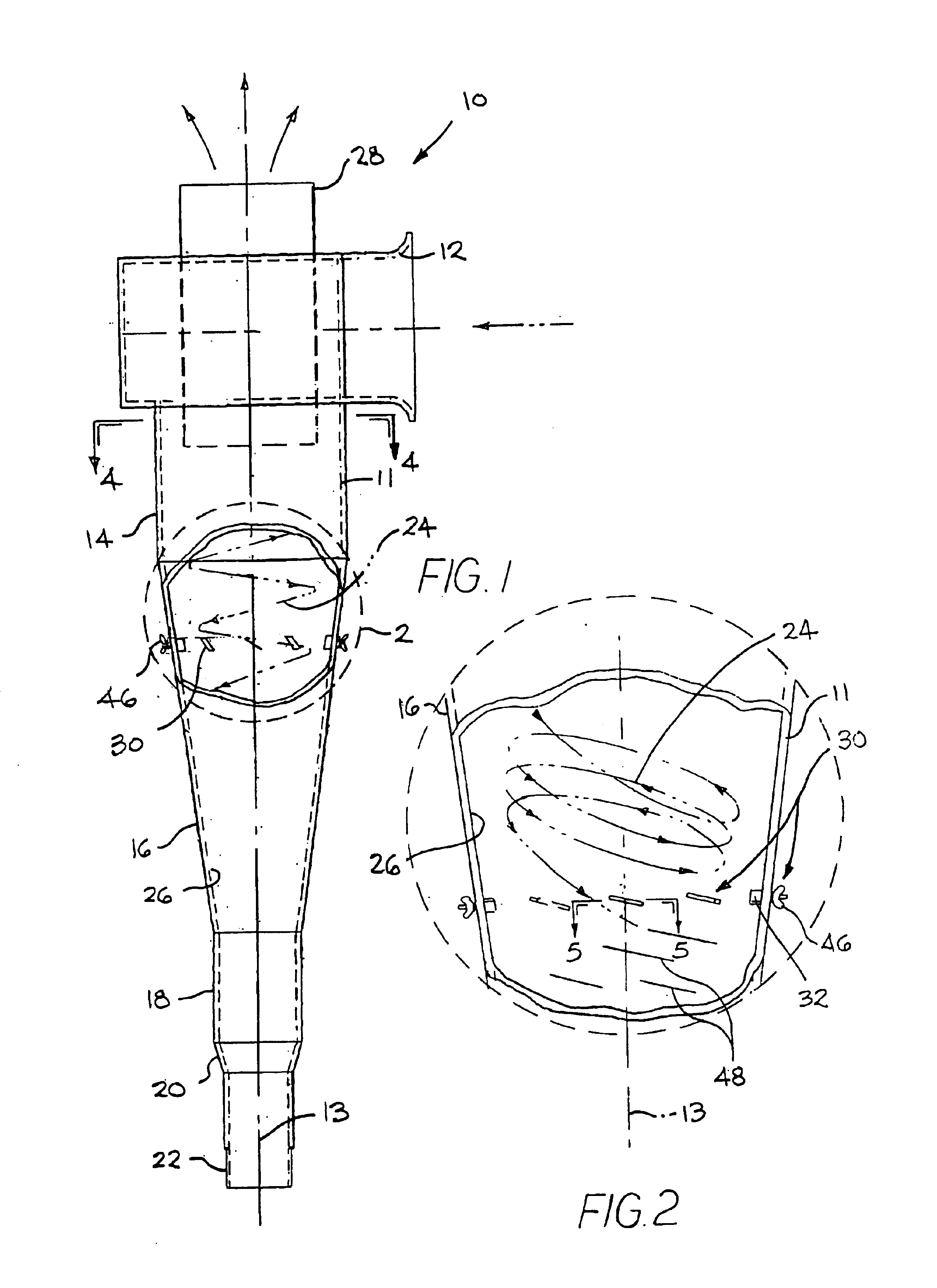
FIG. 1 shows a cyclone separator 10 made in accordance with the present invention. The cyclone separator 10 has a continuous side wall 11, which has a circular cross-section and defines a central vertical axis 13. The side wall 11 defines a tangential inlet 12 to allow a particulate laden gas, such as air, to enter the body of the cyclone separator 10. The side wall 11 of the cyclone separator 10 includes an upper cylindrical section 14, connected to an intermediate frustroconical section 16 (hereinafter referred to simply as the conical section 16), followed by a lower cylindrical section 18. A cylindrical, solids outlet section 22 is connected to the lower cylindrical section 18 via a concentric reducer 20. A cylindrical, clean-gas-outlet section 28 is located at the top of the cyclone separator 10, and this outlet section 28 extends a distance into the body of the cyclone separator 10 as shown in FIG. 1. Typically, particulate laden gas is drawn into and through the cyclone separ...


PUM

PropertyMeasurementUnit
angleaaaaaaaaaa
angleaaaaaaaaaa
angleaaaaaaaaaa

Abstract

A cyclone separator including vanes along the inside wall of the conical section of the separator to regulate the pitch and thus the axial velocity of the gas flow stream in the separator. By adjusting the pitch of the gas flow stream, the collection efficiency of the separator can be optimized so as to minimize the amount of dust particles which are re-entrained in the gas flow stream exiting the separator.

Description

BACKGROUND OF THE INVENTIONThis application claims priority from U.S. Provisional Application Ser. No. 60 / 374,595 filed on Apr. 22, 2002, which is hereby incorporated by reference.The present invention relates to a cyclone separator. More particularly, it relates to a cyclone separator which includes adjustable vanes along the inside surface of the cone of the cyclone separator. These vanes are adjusted in order to direct the gas flow so as to optimize the separation of particulates from the gas flow.Cyclone separators are often used as primary gas pollution control equipment, ahead of baghouses, for instance, to knock out the larger particles and reduce the particulate loading on the baghouse. It is desirable to optimize the performance of the cyclone separator by minimizing the emission of particulates from the cyclone separator so as to minimize the discharge of particulates into the environment, or to reduce the loading on downstream equipment such as baghouses.Current design pr...

Claims


Application Information

Patent Timeline
Patent Type & Authority Patents(United States)
IPC IPC(8): B01D45/16B01D45/12B04C5/103B04C5/00
CPCB04C5/103B01D45/16
Inventor HEUMANN, WILLIAM L.
Owner CECO ENVIRONMENTAL IP INC
Features
  • Generate Ideas
  • Intellectual Property
  • Life Sciences
  • Materials
  • Tech Scout
  • Unparalleled Data Quality
  • Higher Quality Content
  • 60% Fewer Hallucinations
Learn More