
Flexible heating element

a heating element and flexible technology, applied in the direction of cell components, mechanical control devices, instruments, etc., can solve the problems of unavoidable creases in the finished surface, difficult application of known areal or surface heating elements to sharply curved or radiused surfaces, unsightly surfaces, etc., and achieves an acceptable feel for the operator's hand and good aesthetic appearan

Inactive Publication Date: 2005-01-04
GENTHERM GMBH
View PDF5 Cites 49 Cited by
  • Summary
  • Abstract
  • Description
  • Claims
  • Application Information

AI Technical Summary

Benefits of technology

The present invention provides a method for producing surface heating elements having smooth surfaces of good aesthetic appearance when implemented resulting in an acceptable feel to the operator's hand. In addition, the areal heating elements of the present invention are durable.
According to the present invention, a process is provided in which the heating conductor, while retaining a stabilizing margin, is formed out of conductive foil in such a way that the conductor remains connected by webs to the marginal region. A synthetic film is applied to one side of the heating conductor and a two-sided adhesive strip is applied to the other side of the heating conductor. Afterwards, the marginal region is removed and the final contour of the heating conductor is cut out, preferably in such manner that a central web remains. This central web allows the heating element to be manipulated around a curved surface without creasing.

Problems solved by technology

Known areal or surface heating elements are difficult to apply to sharply curved or radiused surfaces, such as the steering wheel or gear shift lever of a motor vehicle.
Creases in the finished surface are all but unavoidable.
Consequently, a control device furnished with a known areal heating element will have an unsightly, corrugated surface, and can provide disagreeable tactile feedback with the operator's hands.
Perspiration from the hands can also penetrate the cover of the surface, corrode the wire, and cause the heating system to fail.

Method used


Image

  • Flexible heating element
  • Flexible heating element
  • Flexible heating element

Examples


Embodiment Construction

While the present invention is described with respect to a heating element and method for making a heating element for application to a steering wheel of a vehicle, the present invention may be adapted and utilized for heating element applications for any curved or contoured surface including: gear shift levers, control knobs, handrails or any contoured surface where heat control and tactile integrity is desired.

In the following description, various operating parameters and components are described for one constructed embodiment. These parameters and components are included as examples and are not meant to be limiting.

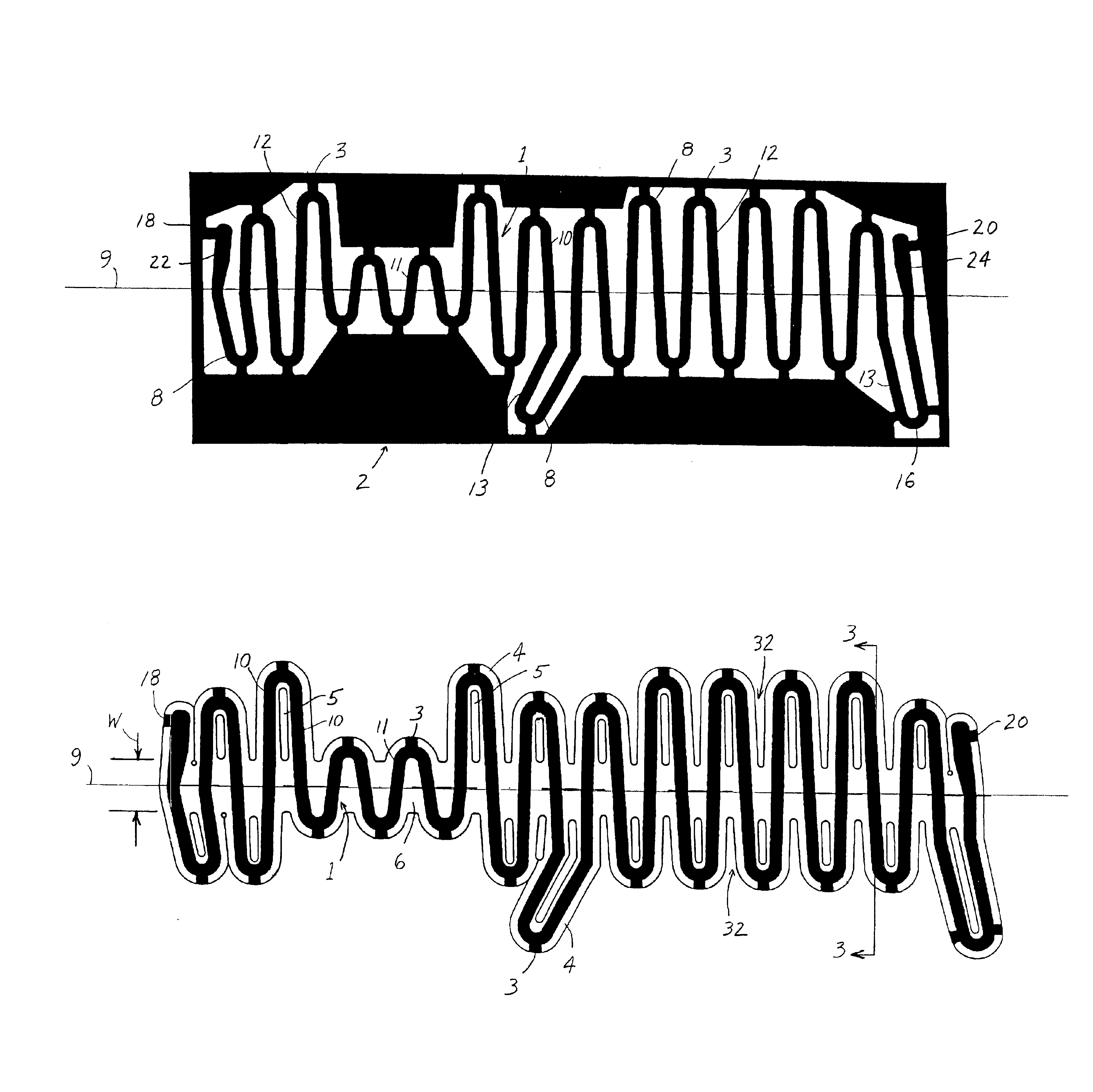
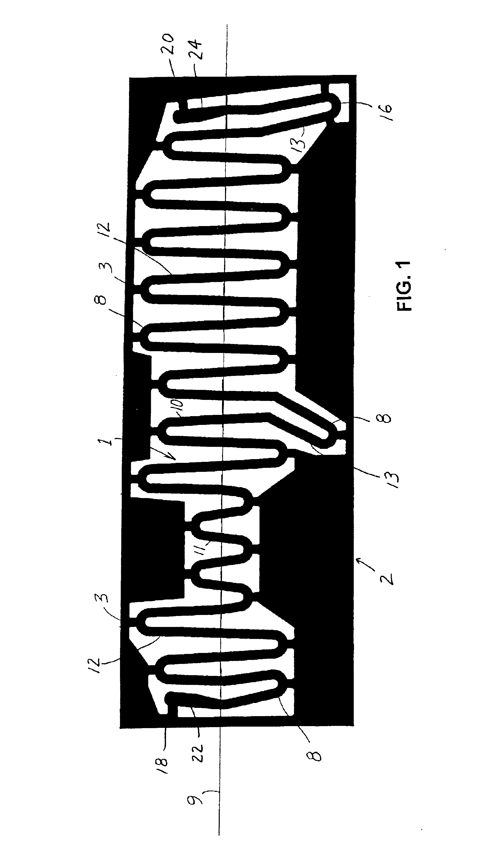
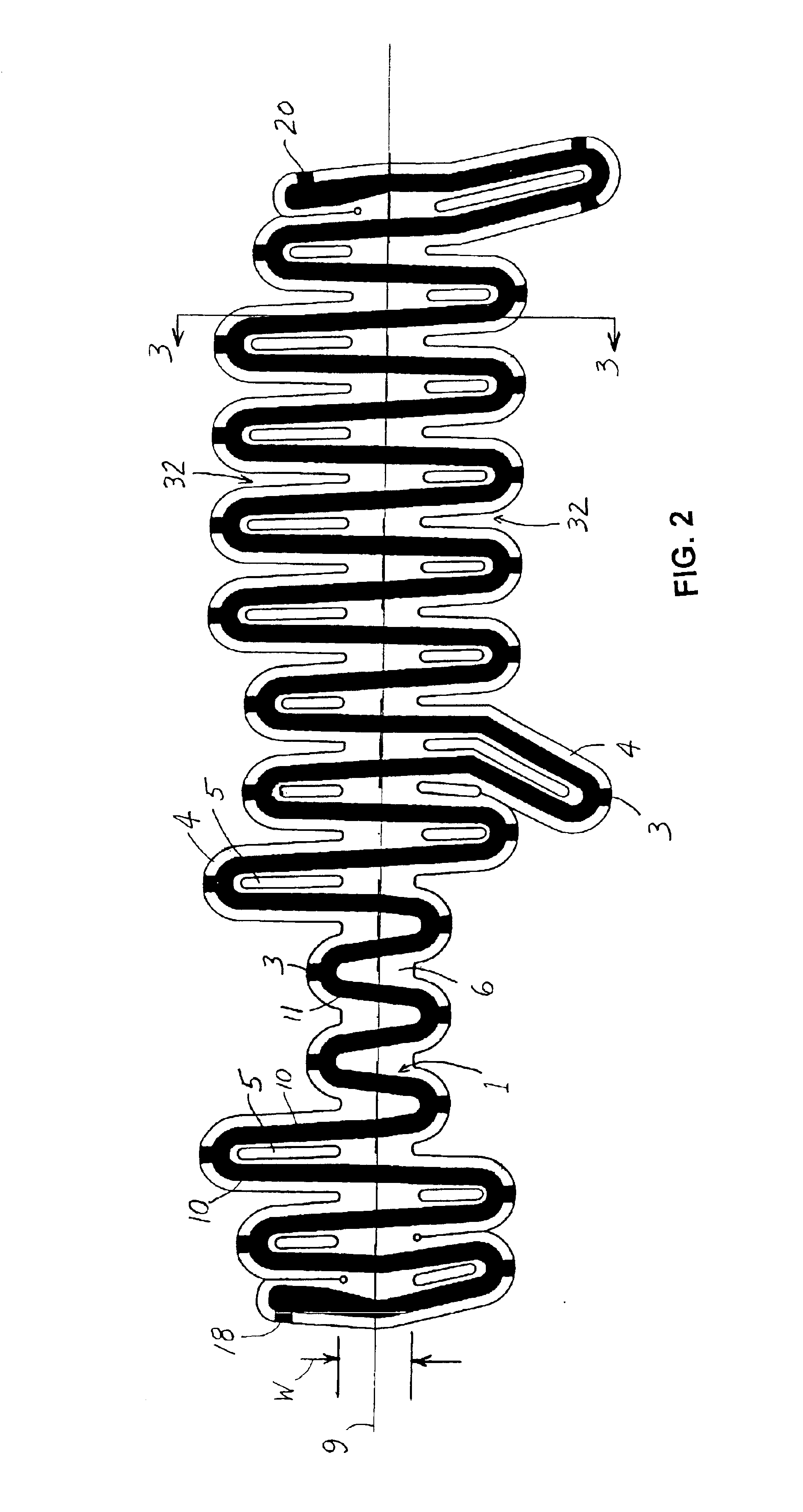
Referring now to the drawings wherein like reference numerals are used to identify identical components in the various views, FIG. 1 shows a top view of a meandering heating conductor 1 in an intermediate stage of the process according to the present invention. The heating conductor 1 is formed out of a conductive synthetic or metal film, but remains connected to a mar...


PUM

PropertyMeasurementUnit
electrical currentaaaaaaaaaa
adhesiveaaaaaaaaaa
angleaaaaaaaaaa

Abstract

A surface-heating element for a curved surface and method of producing a heating element is provided. The heating element includes a continuous, planar conductor arranged along a longitudinal axis including a plurality of turns connected by regions being generally transverse to the longitudinal axis. The conductor including end portions each having a terminal for receiving electrical current. The heating element also includes a film applied to one side of the conductor and configured to substantially follow an outer contour of the conductor. The film and the conductor form a continuous web generally centered about the longitudinal axis, and at least one turn connecting two generally transverse regions extends beyond the continuous web. The heating element may also include an adhesive layer on the other side of the heating element sealingly engaging the film.

Description

TECHNICAL FIELDThe present invention relates to the production of areal heating elements and, in particular, to areal heating elements for heating sharply curved surfaces, such as a steering wheel or a gear shift lever associated with a motor vehicle.BACKGROUNDKnown areal or surface heating elements are difficult to apply to sharply curved or radiused surfaces, such as the steering wheel or gear shift lever of a motor vehicle. Creases in the finished surface are all but unavoidable. Consequently, a control device furnished with a known areal heating element will have an unsightly, corrugated surface, and can provide disagreeable tactile feedback with the operator's hands. Besides the heating conductor, an electrically conductive wire, may be visible on the steering wheel surface and discernable to the operator's hands. Perspiration from the hands can also penetrate the cover of the surface, corrode the wire, and cause the heating system to fail.Accordingly, there is a need for an im...

Claims


Application Information

Patent Timeline
Patent Type & Authority Patents(United States)
IPC IPC(8): B62D1/06F16H59/02H05B3/34H05B3/20
CPCB62D1/065F16H59/0278H05B3/34H05B2203/013Y10T74/20864Y10T74/20834Y10T29/4911Y10T29/49117Y10T29/49099H05B2203/017
Inventor NAGELE, PETER
Owner GENTHERM GMBH
Learn More