Stator of two rotor single stator type electric motor

Inactive Publication Date: 2005-01-04
NISSAN MOTOR CO LTD
View PDF5 Cites 22 Cited by
  • Summary
  • Abstract
  • Description
  • Claims
  • Application Information

AI Technical Summary

Benefits of technology

It is therefore an object of the present invention to provide a stator for use in a two rotor single stator type electric motor

Problems solved by technology

However, it has been revealed that such measures for producing the magnetic bypass resistance brings about an increas

Method used


Image

  • Stator of two rotor single stator type electric motor
  • Stator of two rotor single stator type electric motor
  • Stator of two rotor single stator type electric motor

Examples


first embodiment

In the following, advantages of the stator ST of the first embodiment will be described.

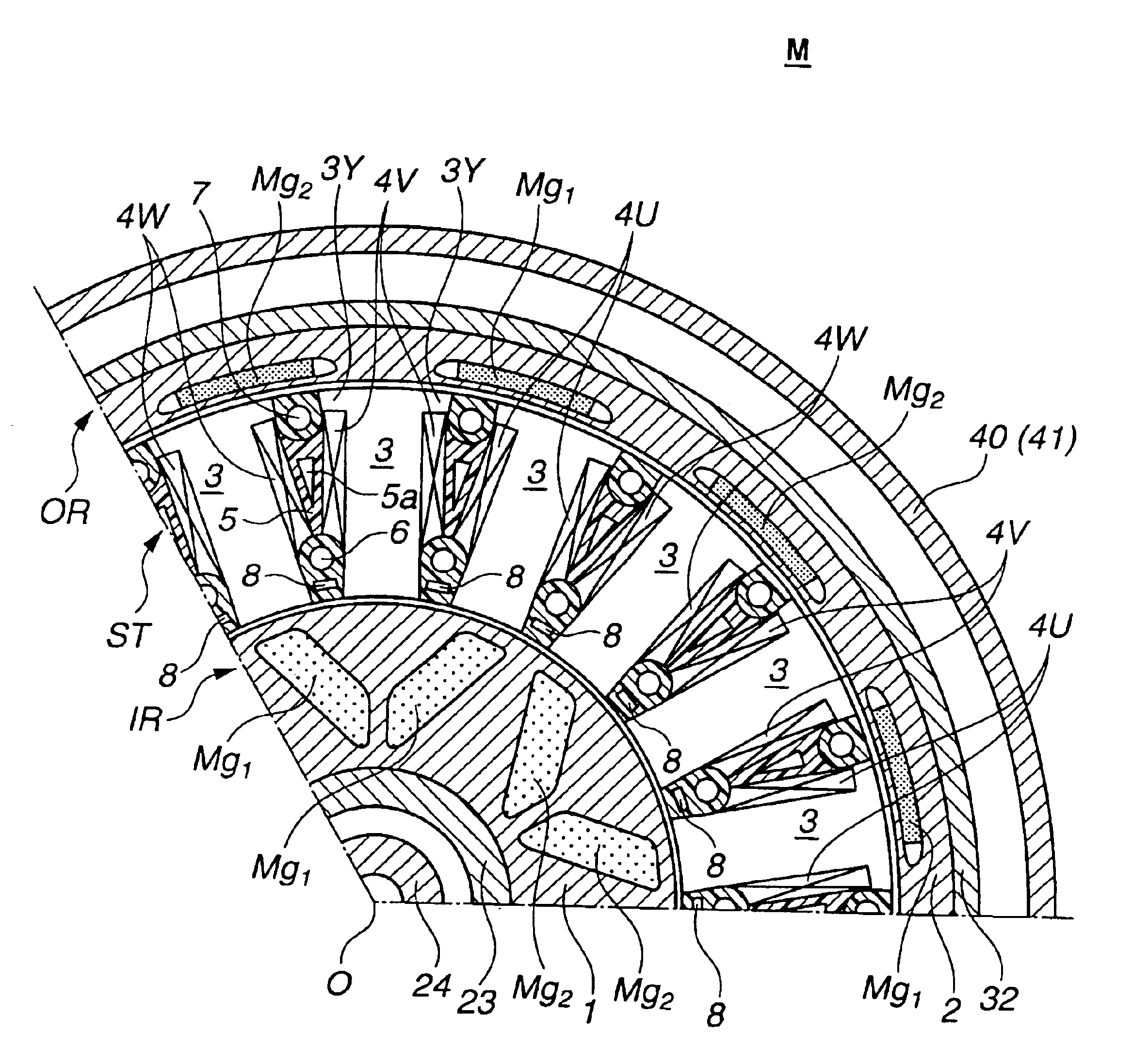
Due to provision of the elongate magnetic plate bars 8 each being positioned between adjacent two of the stator teeth 3 and near inner rotor IR, a desired magnetic bypass resistance is produced. Thus, even when alternation of the magnaflux takes place, a loss caused by eddy current can be reduced. It is to be noted that the laminated structure of the magnetic plate bars 8 exhibits a remarked work for reducing the loss. This advantage is not expected from the bolts 6 and 7 because these are of a solid structure.

Because the elongate magnetic plate bars 8 are members separate from the stator core that includes stator teeth 3, provision of magnetic plate bars 8 to stator ST does not induce a complicated structure of stator ST. Thus, production of stator ST is easily achieved without increasing the cost of the same.

As is described hereinabove, six polar pairs of magnets Mg1 and Mg2 are provided in out...


PUM


Abstract

A stator for use in a two rotor single stator type electric motor includes a stator core including a plurality of stator teeth that are circumferentially arranged around a common axis leaving a plurality of identical spaces each being defined between adjacent two of the stator teeth. Each stator tooth includes a plurality of flat magnetic steel plates that are aligned along the common axis. A plurality of coils are put around the stator teeth respectively. Bolts extend through identical spaces of the stator core for combining the flat magnetic steel plates to have a fixed structure of the stator core. A molded plastic fills the identical spaces of the stator core. A plurality of elongate plate bars extend in the identical spaces through the molded plastic respectively. Each elongate plate bar extends in parallel with the common axis and is constructed of a magnetic material that has an electric resistance higher than the bolts.

Description

BACKGROUND OF INVENTION1. Field of InventionThe present invention relates in general to electric motors, and more particularly to electric motors of a two rotor single stator type which comprises outer and inner rotors which rotate around and within a common stator. More specifically, the present invention is concerned with a stator for the two rotor single stator type electric motor.2. Description of Related ArtOne electric motor of the above-mentioned type is shown in Japanese Laid-open Patent Application (Tokkai) 2000-14086. In the electric motor of this published application, upon feeding a compound electric current to a common stator, two rotors, that is, outer and inner rotors are rotated around and within the common stator respectively. By varying the nature of the compound electric current fed to the stator, rotation of the outer rotor and that of the inner rotor are individually controlled.The stator of the electric motor of the published application comprises a stator core...

Claims


Application Information

Patent Timeline
IPC IPC(8): H02K1/06H02K1/08H02K1/14H02K1/18H02K3/24H02K16/00H02K16/02H02K3/04
CPCH02K1/08H02K1/14H02K1/18H02K16/02H02K3/24
Inventor ARIMITSU, MINORUNAKANO, MASAKI
Owner NISSAN MOTOR CO LTD
Why Eureka
Try Eureka