Image input apparatus

a technology of image input and input apparatus, which is applied in the direction of digital output to print units, instruments, digital computers, etc., can solve the problems of inability to stop the reading operation, the difficulty of halfway stopping the sheet which is being automatically fed, and the inability to transfer image data with a constant period, so as to reduce the time necessary for image data processing

Inactive Publication Date: 2005-01-04
PANASONIC CORP
View PDF4 Cites 6 Cited by
  • Summary
  • Abstract
  • Description
  • Claims
  • Application Information

AI Technical Summary

Benefits of technology

Therefore, since the image data is transferred in the transfer mode in which the periodic transfer can be assured, the image data read by the reading means is periodically transferred to the other apparatus. Also, the image data to be transferred can be accurately and successively transferred twice or more, and thus the successively transferred image data can be immediately used for the case in which error occurs when the image data is transmitted and received. In other words, even the other apparatus to which the image data is transferred can decrease the time necessary for the image data to be processed.

Problems solved by technology

At this time, in the case of the image scanner using an automatic draft feeder (ADF), it is very difficult to halfway stop the sheet which is being automatically fed.
Therefore, once the manuscript image starts to be read, the reading operation cannot be stopped until one sheet of manuscript image is finished to read.
When the image data is transferred to the computer, it is necessary to secure the right to use the bus each time the computer sends to the transfer request, and thus the image data cannot be transferred with a constant period.
Therefore, when the image scanner cannot secure the right to use the bus for the image data transfer, it takes time for the image data to be completely transferred.
Thus, it is a neck to provide this memory when we consider reducing the cost of the image scanner (the first problem).
If one of the sheets cannot be started to read when the bus is busy, the processing speed cannot be increased.
However, the larger the number of sheets is read, the larger the memory capacity becomes (the second problem).
In addition, when the image scanner cannot secure the right to use the bus for data transfer, time is taken for the image data to be completely transferred.
Moreover, error checking is performed when the transferred image data is transmitted and received.
Therefore, it is again a neck to provide this memory when we consider reducing the cost of the image scanner (the third problem).

Method used


Image

  • Image input apparatus
  • Image input apparatus
  • Image input apparatus

Examples


first embodiment

(First Embodiment)

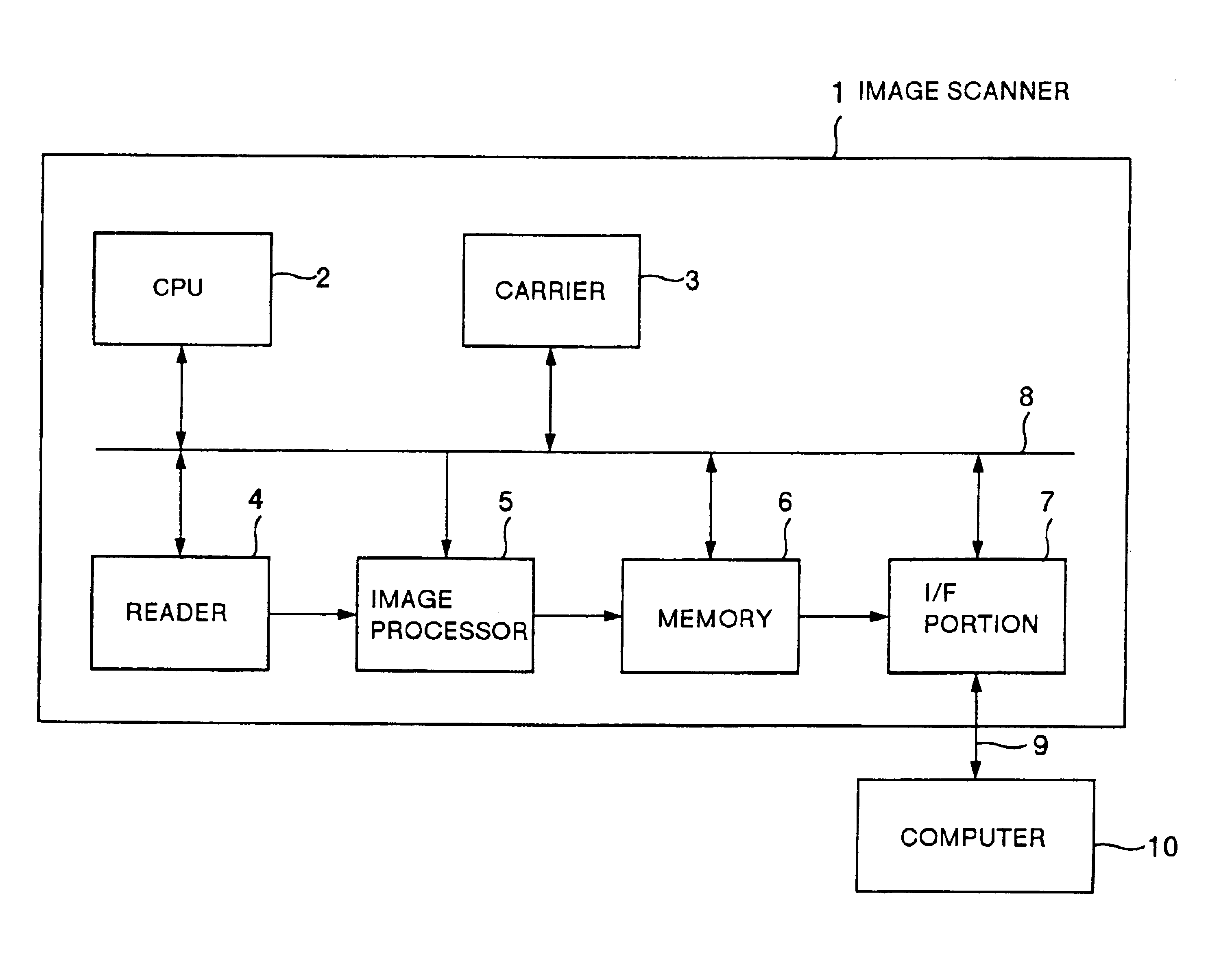
FIG. 1 is a diagram showing a hardware structure of an image input apparatus according to a first embodiment of the present invention.

As shown in FIG. 1, an image scanner 1 as the image input apparatus according to the first embodiment is connected via a bus to a computer 10 as another apparatus. The IEEE standard 1394 (IEEE: Institute of Electrical and Electronic Engineers, Inc.) interface for fast serial transmission is used as communication means for performing a data communication between the image scanner 1 and the computer 10.

The image scanner 1 includes a CPU 2 as control means for controlling the whole image scanner 1; a carrier 3 for feeding, carrying and discharging sheets of manuscript image; a reader 4 as reading means for reading images on the sheets of manuscript and converting them into image data; an image processor 5 for converting the analog image data from the reader 4 into digital image data, and processing to convert the digital image data to b...

second embodiment

(Second Embodiment)

The hardware structure of an image input apparatus according to a second embodiment of the present invention is the same as that of the image input apparatus according to the first embodiment shown in FIG. 1 except that the carrier 3 functions as supply means for successively supplying, carrying and discharging a plurality of manuscript sheets one by one. Therefore, the structure will not be described in detail.

The image transfer in the image input apparatus according to the second embodiment will be described with reference to FIG. 12.

First, the setting data for the reading conditions is transferred from the computer 10 to the image scanner 1 in the asynchronous transfer mode. The image scanner 1, when receiving this setting data and finishing the setting of the apparatus, sends OK to the computer 10 in the asynchronous transfer mode. At this time, the image scanner 1 detects the presence or absence of a manuscript sheet to be fed to the carrier 3, and transfers ...

third embodiment

(Third Embodiment)

The hardware structure of an image input apparatus according to a third embodiment of the present invention is the same as that of the image input apparatus according to the first embodiment shown in FIG. 1, and will not be described in detail.

The image transfer in the image input apparatus according to the third embodiment will be described with reference to FIG. 16.

First, the setting data for the reading conditions is transferred from the computer 10 to the image scanner 1 in the asynchronous transfer mode. When receiving this setting data and finishing to set the apparatus, the image scanner 1 sends OK to the computer 10 in the asynchronous transfer mode. The computer 10 receives this reply, and issues the reading-start command to the image scanner 1 in the asynchronous transfer mode. The image scanner 1, when receiving the reading-start command, sends OK to the computer 10 in the asynchronous transfer mode. Then, the image scanner 1 acquires the right to perfor...


PUM


Abstract

An image input apparatus includes a reading unit for reading a manuscript image, and a communication unit for transferring the image data, which is read by the reading unit, and control data to another apparatus. The communication unit has a first mode in which a periodic data transfer can be assured, and a second mode in which the periodic data transfer cannot be assured. The communication unit transfers the image data in the first mode, and the control data in the second mode.

Description

BACKGROUND OF THE INVENTIONThe present invention relates to an image input apparatus connected to another apparatus via a bus, and particularly to an image input apparatus which reads a manuscript image to transfer it to another apparatus.The image input apparatus such as an image scanner is connected via a bus to other apparatus such as a higher-level apparatus of a computer, and reads a manuscript image such as a picture, a photograph and a document to transfer the read image data to the other apparatus. The transfer of the image data is performed by use of a parallel interface such as Centronics-conformable interface and SCSI (Small Computer System Interface) or a serial interface such as RS-232C and RS-422.In the communication systems using these interfaces, the asynchronous communication is performed. When the communication is performed with another peripheral equipment connected to these interfaces, the image scanner makes the mediation for securing the right to use the bus ea...

Claims


Application Information

Patent Timeline
Patent Type & Authority Patents(United States)
IPC IPC(8): G06F15/00H04N1/00
CPCH04N1/00127H04N1/00204H04N2201/0015H04N2201/0072H04N2201/0046H04N2201/0049H04N2201/0041
Inventor MATSUZOE, SUSUMUNAKAYAMA, TAKESHI
Owner PANASONIC CORP
Why Eureka
Try Eureka