
Head gimbal assembly with a ground or source voltage lead conductor

a lead conductor and gimbal technology, applied in the direction of maintaining the alignment of the head carrier, recording information storage, instruments, etc., can solve the problems of mr read head element damage, inductive electromotive force to produce, deterioration of reading characteristics, etc., and achieve the effect of high data rate recording

Inactive Publication Date: 2005-01-04
TDK CORPARATION
View PDF3 Cites 55 Cited by
  • Summary
  • Abstract
  • Description
  • Claims
  • Application Information

AI Technical Summary

Benefits of technology

It is therefore an object of the present invention to provide an HGA, whereby change in characteristics of a read head element and also destruction of the read head element can be prevented from occurring even if a write current with steep rising and falling edges is used to achieve a high data rate recording.
Another object of the present invention is to provide an HGA, whereby change in characteristics of a read head element and also destruction of the read head element can be prevented from occurring without substantially increasing the manufacturing cost.
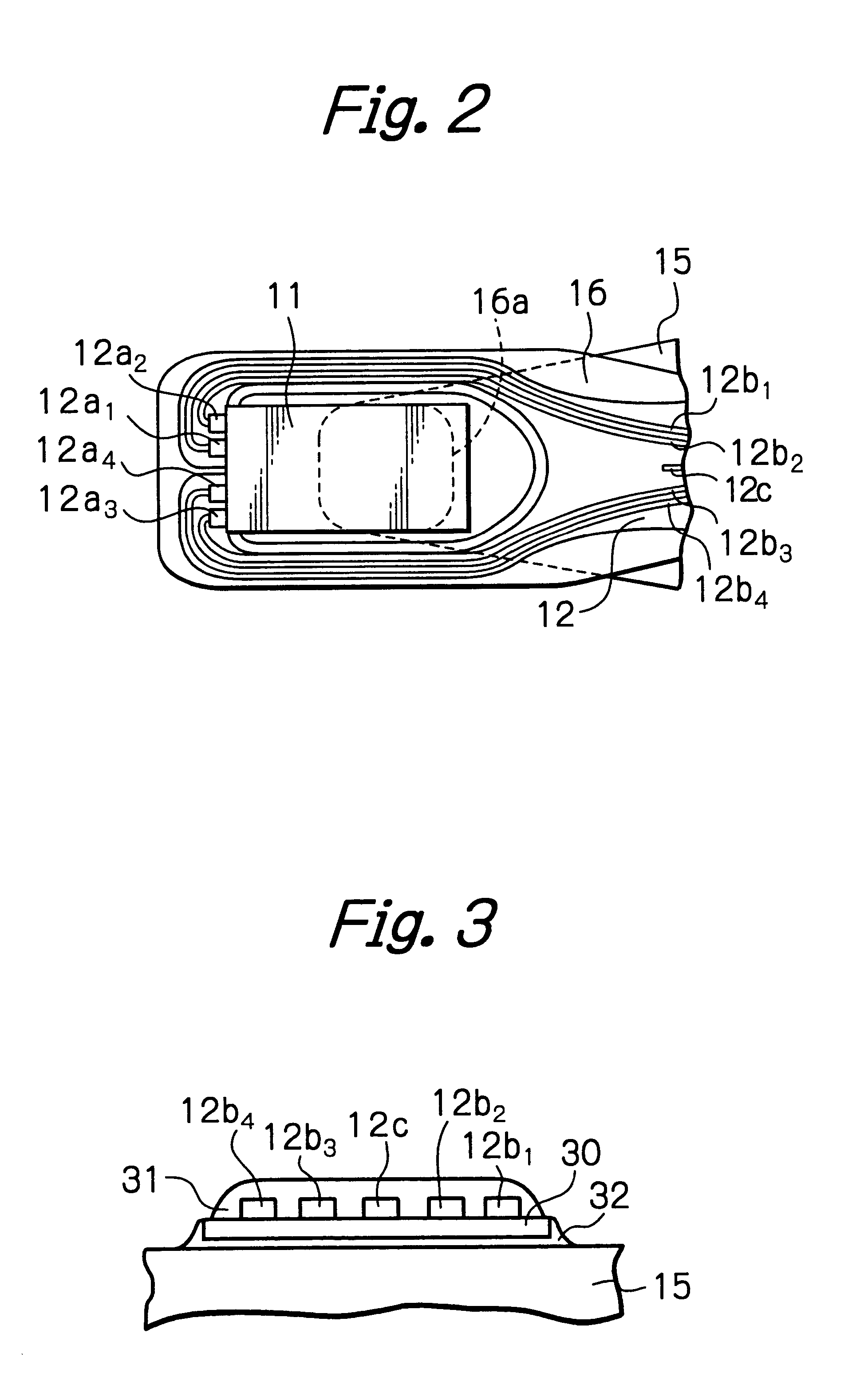
The GND or Vcc conductor is inserted between the first and second trace conductors. Since the GND or Vcc conductor acts as a shield pattern between the first and second trace conductors, no inductive electromotive force will be generated on the second trace conductors even if harmonic components occur on the first trace conductors due to overshoots produced at the rising and / or falling edges of the write current. Thus, change in characteristics of the read head element and also destruction of the read head element due to the inductive electromotive force can be prevented from occurring even if a write current with steep rising and falling edges is used to achieve a high data rate recording. Furthermore, since this can be achieved only by additionally forming one GND or Vcc conductor when fabricating the trace conductors, no additional process is necessary and therefore manufacturing cost will not substantially increase.

Problems solved by technology

However, if the rising and falling times of the write current are shortened, overshoot may occur at the rising or falling edge causing inductive electromotive force to produce on a trace conductor or a circuit adjacent to the write signal lines due to harmonic components of occurred on the write signal lines.
If the inductive electromotive force is produced on the read signal lines, the read head element, particularly a magnetoresistive effect (MR) read head element, connected thereto may deteriorate its reading characteristics.
In the worst case, the MR read head element may be destroyed due to the inductive electromotive force.

Method used


Image

  • Head gimbal assembly with a ground or source voltage lead conductor
  • Head gimbal assembly with a ground or source voltage lead conductor
  • Head gimbal assembly with a ground or source voltage lead conductor

Examples


Embodiment Construction

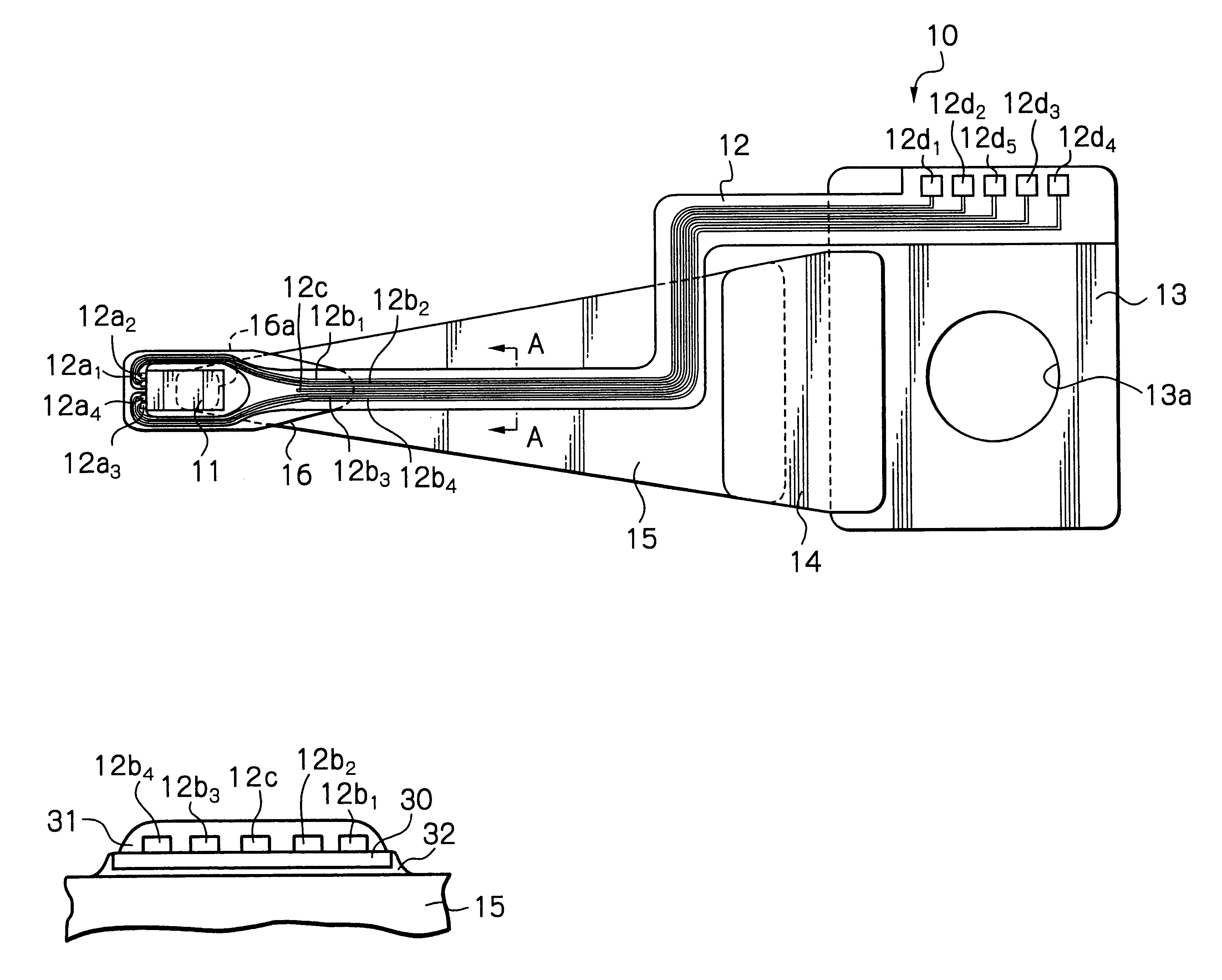
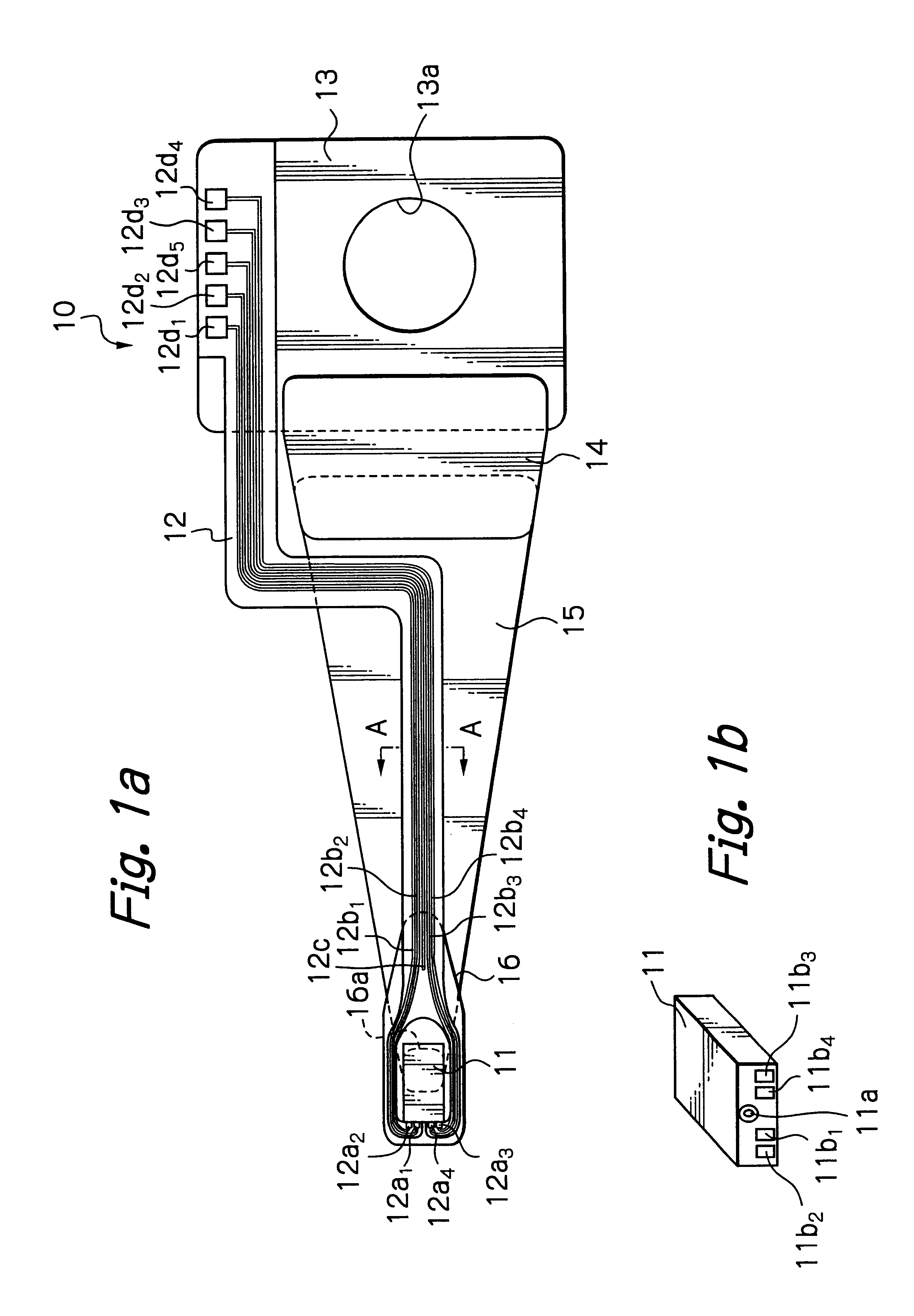
FIG. 1a illustrates the whole structure of an HGA seen from a slider-mounting surface in a preferred embodiment according to the present invention, FIG. 1b illustrates a magnetic head slider in this embodiment, FIG. 2 illustrates an enlarged view of a top end section of a suspension in this embodiment, and FIG. 3 illustrates an A—A line sectional view of FIG. 1a.

As shown in FIGS. 1a, 1b and 2, the HGA in this embodiment has a suspension 10, a magnetic head slider 11 provided with a thin-film write head element 11a and a thin-film MR read head element 11a, fixed to a top end section of the suspension 10 and a FPC or lead conductor member 12 adhered on the suspension 10. Four terminal electrodes 11b1 to 11b4 connected to the thin-film write head element and the thin-film read head element are electrically connected to four head connection pads 12a1 to 12a4 of the FPC 12 by ball bonding using for example Au balls or solder balls, respectively.

The suspension 10 is substantially formed ...


PUM

PropertyMeasurementUnit
thicknessaaaaaaaaaa
thicknessaaaaaaaaaa
thicknessaaaaaaaaaa

Abstract

An HGA has a head slider including at least one write head element with terminal electrodes and at least one read head element with terminal electrodes, a suspension for supporting the head slider at a top end section thereof, and a lead conductor member including first trace conductors and second trace conductors. One ends of the first trace conductors are electrically connected to the terminal electrodes of the at least one write head element, and one ends of the second trace conductors are electrically connected to the terminal electrodes of the at least one read head element. At least part of the lead conductor member is fixed to the suspension. The lead conductor member further includes a ground (GND) or source voltage (Vcc) conductor inserted between the first and second trace conductors.

Description

FIELD OF THE INVENTIONThe present invention relates to a head gimbal assembly (HGA) provided with a suspension for supporting a head slider having a write head element and a read head element used in a magnetic hard disk drive (HDD) unit or in an optical disk drive unit for example.DESCRIPTION OF THE RELATED ARTIn an HDD, magnetic write head elements for writing magnetic information onto magnetic hard disks and magnetic read head elements for reading magnetic information from the magnetic hard disks are in general formed on magnetic head sliders flying in operation above the rotating magnetic disks. The sliders are supported at top end sections of suspensions of HGAs, respectively.In each HGA, one ends of two pairs of signal lines are electrically connected to a pair of terminal electrodes of the magnetic write head element and to a pair of terminal electrodes of the magnetic read head element formed on the magnetic head slider, respectively. These four signal lines run along the su...

Claims


Application Information

Patent Timeline
Patent Type & Authority Patents(United States)
IPC IPC(8): G11B5/48G11B5/17G11B5/39G11B5/60G11B21/21
CPCG11B5/4853
Inventor SHIRAISHI, MASASHIKAMIGAMA, TAKEHIRO
Owner TDK CORPARATION
Learn More