
Method and apparatus for packet network tunnel management

a packet network and tunnel management technology, applied in the field of packet networks, can solve the problems of inefficient allocation of packet network resources (i.e., bandwidth utilization), uncoordinated creation of packet network tunnels, and increased network costs

Inactive Publication Date: 2005-01-04
CIENA +1
View PDF5 Cites 17 Cited by
  • Summary
  • Abstract
  • Description
  • Claims
  • Application Information

AI Technical Summary

Benefits of technology

Typically, a packet network can comprise many packet network tunnels at any moment, and if each edge router established its own packet network tunnels without regard to the packet network tunnels created by other edge routers, then the packet network's resources (i.e., bandwidth utilization) will be inefficiently allocated and results in a more costly network since the network utilization is suboptimal. The result is that although the packets in packet network tunnels move through the network in an unimpeded fashion, the haphazard and uncoordinated creation of packet network tunnels exacerbates the congestion and delay for packets that are not carried in tunnels.
Therefore, in accordance with the illustrative embodiment, each of routers in the illustrative embodiment is capable of proposing, and establishing if possible, one or more detour tunnels around the failure without the knowledge or consent of the tunnel manager. This is advantageous because it enables the packet network to address failures quickly.
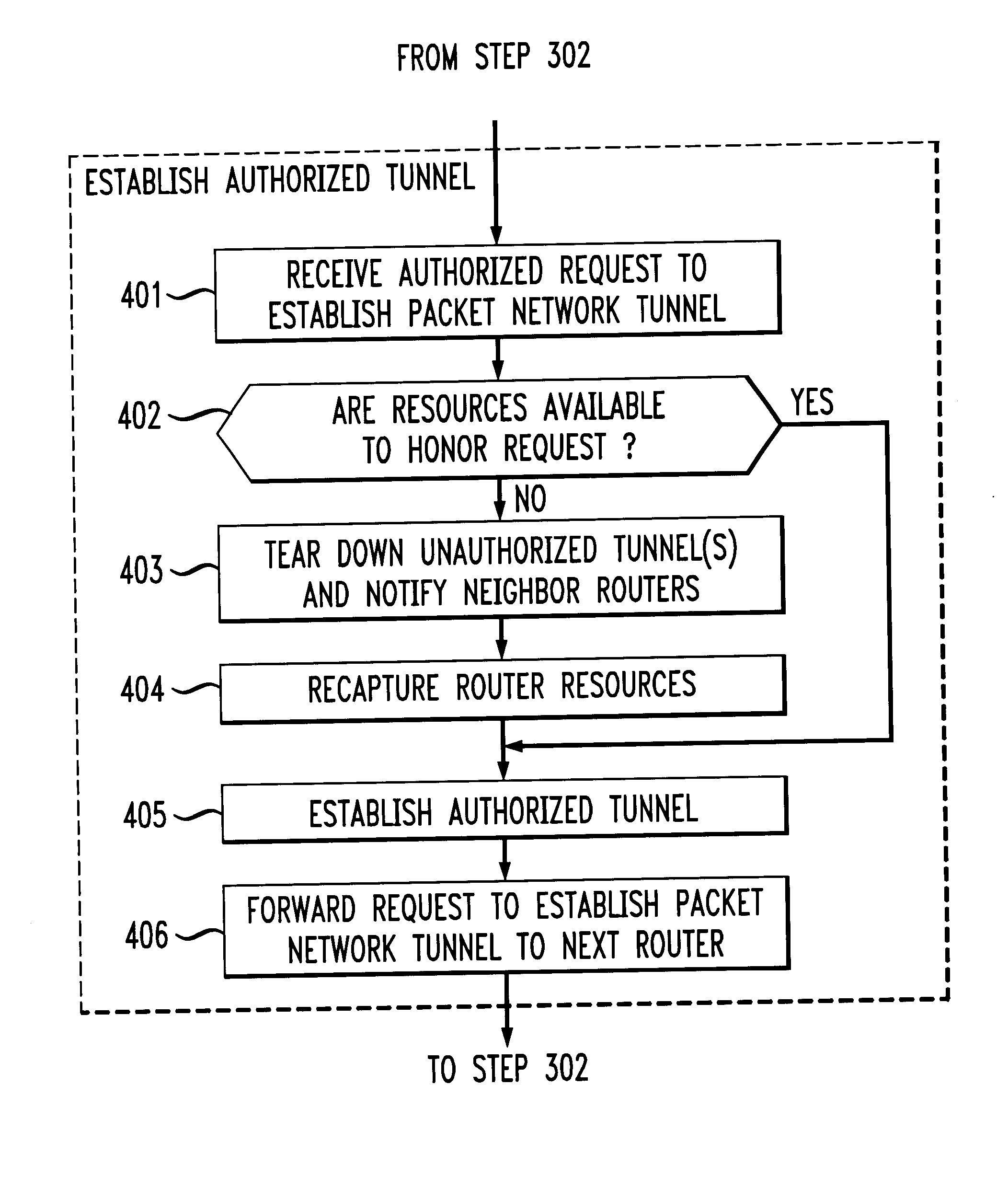
The illustrative embodiment of the present invention overcomes this dilemma by prioritizing the establishment and maintenance of packet network tunnels so that any packet network tunnel “authorized” by the tunnel manager has precedence over router resources over any packet network tunnel that is initiated by a router without the authorization of the tunnel manager. The germane consequence of this precedence is that when the tunnel manager directs the establishment of a packet network tunnel, but a router in the proposed tunnel has insufficient resources to allocate to the proposed tunnel because its resources are consumed by an existing “unauthorized” tunnel, the unauthorized tunnel is torn down at the router and its resources are cannibalized for use by the authorized tunnel. This precedence of authorized packet network tunnels over unauthorized packet network tunnels enables individual routers to address temporary failures in real-time, while enabling the tunnel manager to maintain control over the packet network and without having to keep the tunnel manager apprised of router and link failures and restorations in real-time.

Problems solved by technology

Typically, a packet network can comprise many packet network tunnels at any moment, and if each edge router established its own packet network tunnels without regard to the packet network tunnels created by other edge routers, then the packet network's resources (i.e., bandwidth utilization) will be inefficiently allocated and results in a more costly network since the network utilization is suboptimal.
The result is that although the packets in packet network tunnels move through the network in an unimpeded fashion, the haphazard and uncoordinated creation of packet network tunnels exacerbates the congestion and delay for packets that are not carried in tunnels.

Method used


Image

  • Method and apparatus for packet network tunnel management
  • Method and apparatus for packet network tunnel management
  • Method and apparatus for packet network tunnel management

Examples


Embodiment Construction

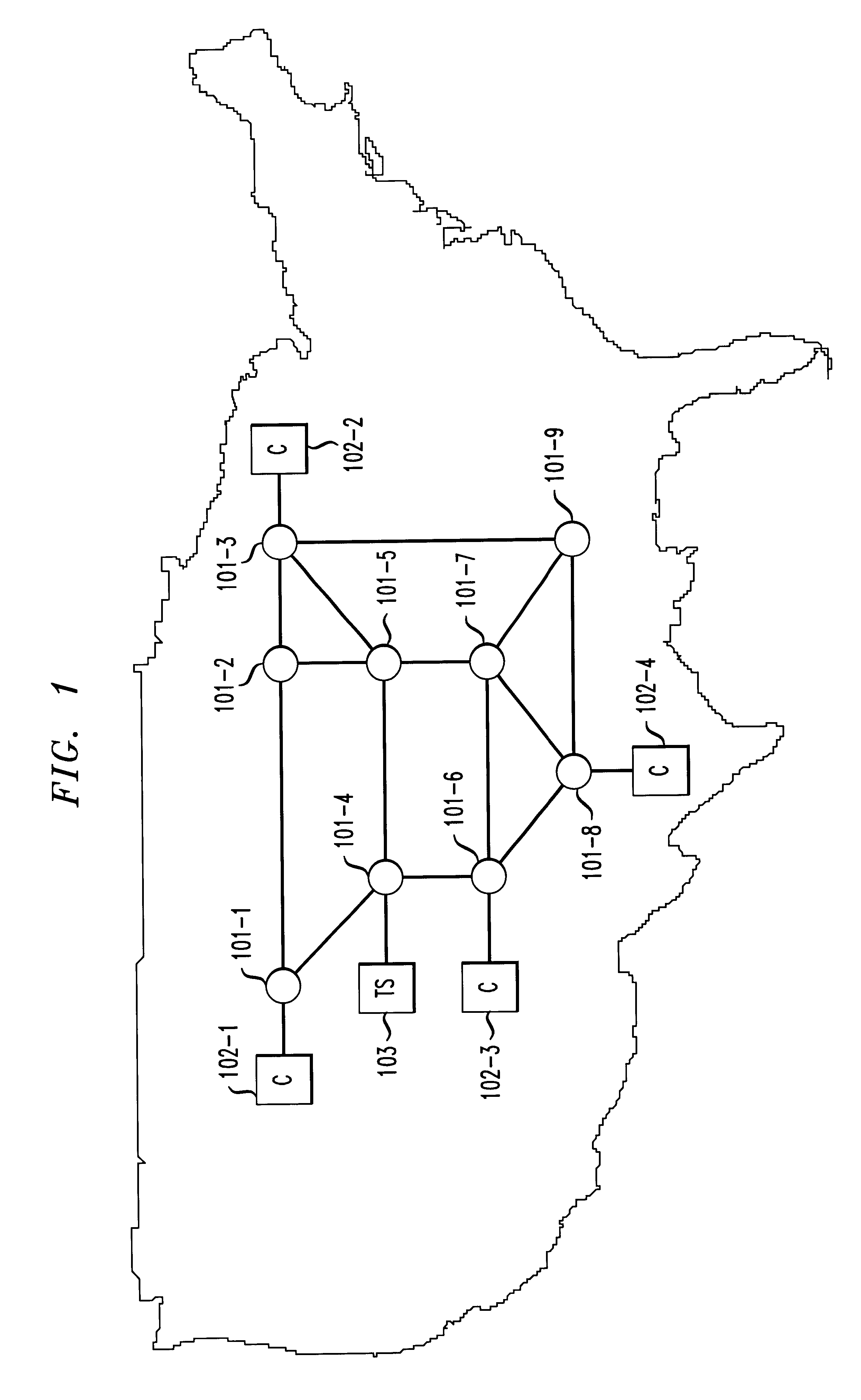
FIG. 1 depicts a packet network in accordance with the illustrative embodiment of the present invention, which comprises nine routers, router 101-1 through 101-9, that are interconnected with bi-directional telecommunications links as shown. Although the illustrative embodiment is depicted with only nine routers, it will be clear to those skilled in the art how to make and use embodiments of the present invention that comprise any number of routers that are interconnected in any topology.

Although the packet network depicted in FIG. 1 is represented as spanning a substantial portion of the continental United States, embodiments of the present invention can be either a local-area network (often called a “LAN”) or a wide-area network (often called a “WAN”). Furthermore, embodiments of the present invention can be a part of the Internet, or connected to the Internet. As will be clear to those skilled in the art, embodiments of the present invention can use any protocol suite (e.g., TCP / ...


PUM


Abstract

Systems and techniques for enabling packet networks to carry time-sensitive data in an efficient manner are described. A packet traverses a packet network through the creation of a packet network tunnel. Each router can propose, and establish if possible, a detour tunnel around the failure without the knowledge or consent of a tunnel manager. Establishment and maintenance of packet network tunnels is also prioritized so any packet network tunnel authorized by the tunnel manager has precedence over any packet network tunnel initiated by a router without the authorization of the tunnel manager.

Description

FIELD OF THE INVENTIONThe present invention relates to packet networks in general, and, more particularly, to a technique for managing the establishment and maintenance of packet network tunnels in a packet network.BACKGROUND OF THE INVENTIONIn a packet network, the finite speed of light and the finite speed at which routers can operate precludes the traversal of a packet from one side of the network to another instantaneously. Therefore, there is always some delay between when a transmitting network terminal transmits a packet and when the receiving network terminal receives the packet.In some cases, this delay is unimportant. For example, some data (e.g., most e-mail messages, etc.) is not perishable or highly time-sensitive and the sender and receiver of the data might consider it unimportant whether the packet takes 5 milliseconds, 5 seconds or even 5 minutes to traverse the network. In contrast, other data (e.g., voice, full-motion video, instant messaging, etc.) is perishable ...

Claims


Application Information

Patent Timeline
IPC IPC(8): H04L12/56H04L12/46
CPCH04L12/4633H04L45/60H04L45/302
Inventor DEJAGER, DALE SCOTT
Owner CIENA
Learn More