
Engine torque control with desired state estimation

a torque control and desired state technology, applied in the direction of electric control, speed sensing governors, combustion engines, etc., can solve the problems of delay in area opening, controller does not have lead information, and may occur undesirable time delays

Active Publication Date: 2005-01-11
GM GLOBAL TECH OPERATIONS LLC
View PDF5 Cites 62 Cited by
  • Summary
  • Abstract
  • Description
  • Claims
  • Application Information

AI Technical Summary

Benefits of technology

An engine control system according to the invention includes an engine having a manifold. A controller calculates a desired area based on a desired manifold absolute

Problems solved by technology

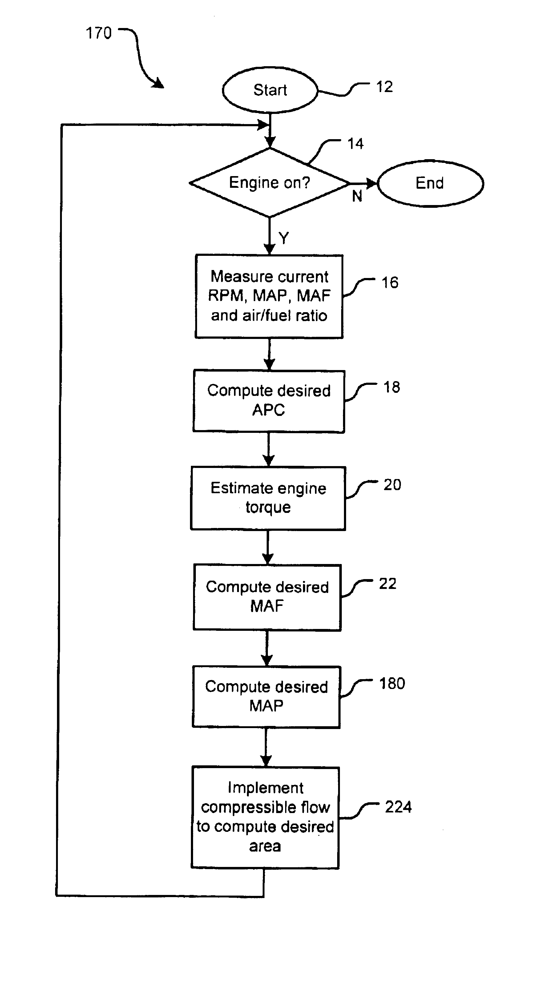
Under transient conditions, the controller does not have lead information enabling fast torque control response.
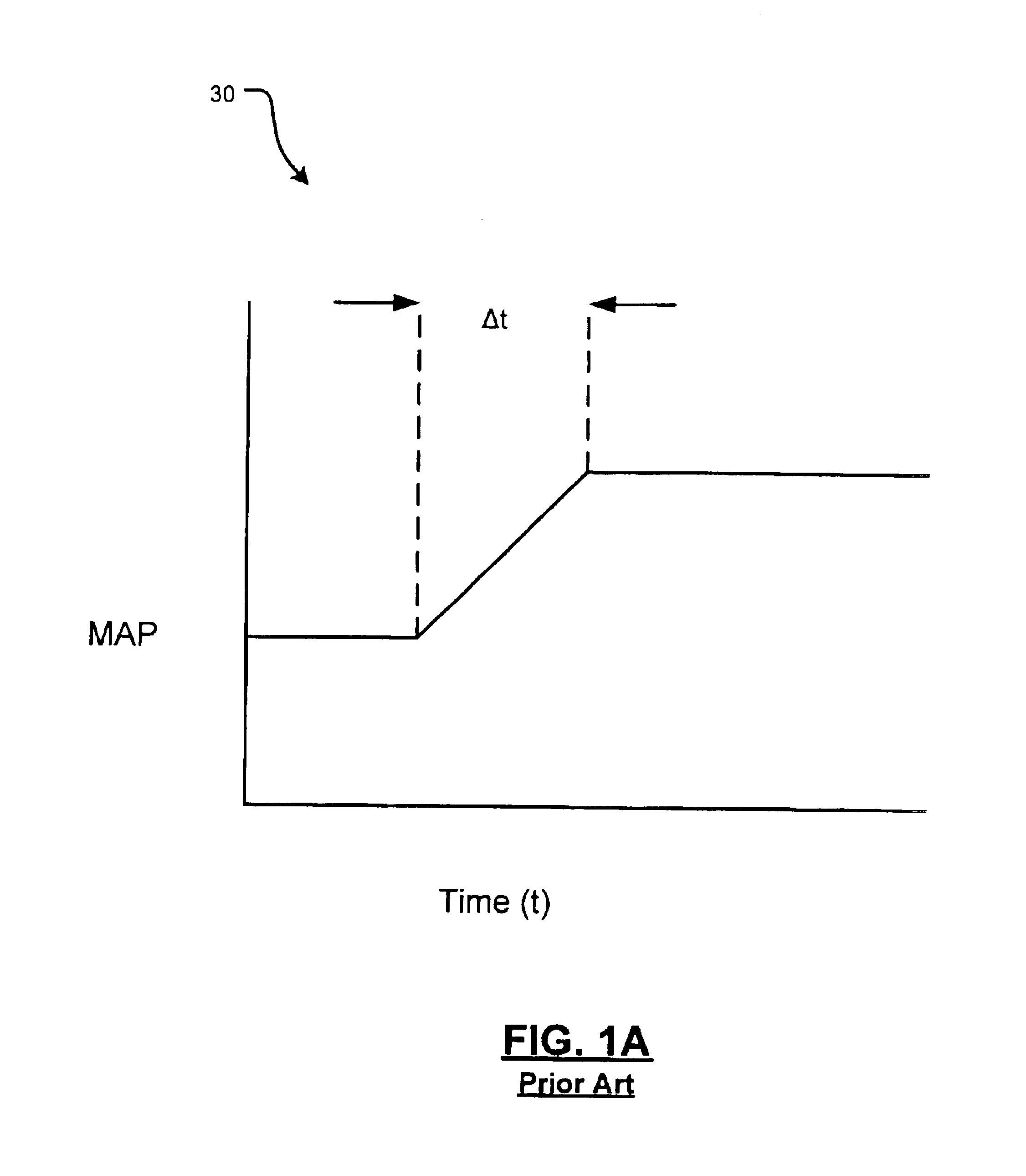
In this regard, an undesirable time delay may occur while correcting MAP and RPM to a desired level.
In this way, MAP will grow from idle to wide open throttle causing a delay in area opening.
As a result, equation (5) will not provide an instantaneous change in area.
A similar undesirable time delay may also result during engine torque control for RPM correction.

Method used


Image

  • Engine torque control with desired state estimation
  • Engine torque control with desired state estimation
  • Engine torque control with desired state estimation

Examples


Embodiment Construction

The following description of the preferred embodiment(s) is merely exemplary in nature and is in no way intended to limit the invention, its application, or uses. For purposes of clarity, the same reference numbers will be used in the drawings to identify similar elements.

Referring now to FIG. 2, an engine control system 110 according to the present invention includes a controller 112 and an engine 116. The engine 116 includes a plurality of cylinders 118 each with one or more intake valves and / or exhaust valves (not shown). The engine 116 further includes a fuel injection system 120 and an ignition system 124. An electronic throttle controller (ETC) 26 adjusts a throttle area of an intake manifold 28 based upon a position of an accelerator pedal (not shown) and a throttle control algorithm that is executed by the controller 112. One or more sensors 134 and 132 such as a manifold pressure sensor and / or a manifold air temperature sensor sense pressure and / or air temperature in the in...


PUM


Abstract

An engine control system and method according to the invention controls torque in an internal combustion engine. Engine parameters are measured and an engine torque is estimated. A desired air per cylinder of the engine is calculated. A desired manifold absolute pressure of a manifold of the engine is calculated based on a function of engine torque. A desired RPM of the engine is calculated based on a measured engine RPM and a reference torque of the engine. A desired area is calculated based on the desired manifold absolute pressure. The desired area is implemented into the controller to control torque output of the engine.

Description

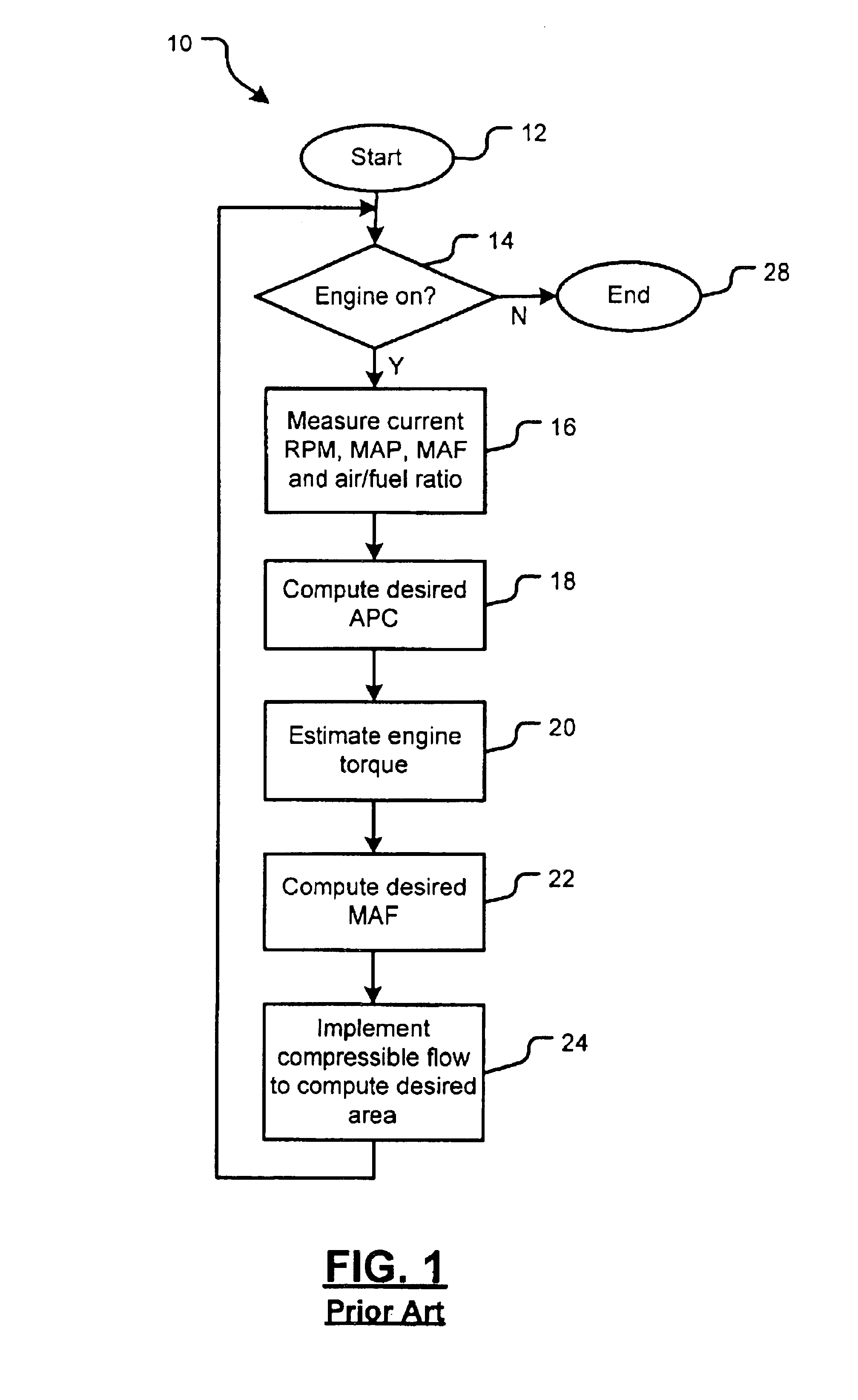
FIELD OF THE INVENTIONThe present invention relates to engine control systems, and more particularly to an engine control system for improving torque control during transient and steady state operation.BACKGROUND OF THE INVENTIONReferring now to FIG. 1, an exemplary method for controlling torque of an engine is shown generally at 10. Torque control begins with step 12. In step 14, control determines if the engine is operating. If the engine is operating, instantaneous RPM (R), manifold absolute pressure (MAP), mass air flow (MAF) and air / fuel ratio (AF) are measured in step 16. If the engine is not operating, control ends in step 28. In step 18, a desired air per cylinder (APCdes) is estimated based on an inverse function of torque. APCdes is determined based on parameters measured in step 16 and other measured values. APCdes may be characterized by the following equation:APCdes=Tapc−1(Tref,R,S,D,AF,OT,Ω)  (1) Where Tref is reference torque, S is spark, D is dilution based on exhaus...

Claims


Application Information

Patent Timeline
IPC IPC(8): F02D41/06F02D41/00F02D41/14F02D41/10F02D11/10
CPCF02D11/105F02D41/0002F02D41/068F02D41/1497F02D41/10Y02T10/42F02D2250/21Y02T10/40
Inventor LIVSHIZ, MICHAELCHYNOWETH, SCOTT J.
Owner GM GLOBAL TECH OPERATIONS LLC
Learn More