Electrical connector box and assembly method thereof

a technology of electrical connectors and boxes, which is applied in the direction of testing/measuring connectors, coupling devices, coupling devices, etc., can solve the problems of limited circuit connections, design that does not lend itself well to modifying circuit connections, and restrict the freedom with which circuit connection patterns can be laid out, so as to simplify the assembly procedure of wire harnesses, reduce the number of locations where wires are placed, and facilitate the effect of circuit connection alteration

Inactive Publication Date: 2005-01-11
SUMITOMO WIRING SYST LTD
View PDF15 Cites 28 Cited by
  • Summary
  • Abstract
  • Description
  • Claims
  • Application Information

AI Technical Summary

Benefits of technology

Taking the above-described drawbacks into consideration, the present invention provides an improved electrical connector box constructed to allow easy alteration of circuit connections, to reduce the number of locations where wires are connected in the wiring harness, and to simplify the wire harness assembly procedure.

Problems solved by technology

This type of conventional connector box requires that the wires to be connected are initially inserted into and anchored to a single connector, thus restricting the freedom with which the circuit connection pattern can be laid out, and often necessitating that long lengths of wires be used.
Moreover, this design does not lend itself well to modifying circuit connections due to the necessity of changing the wires in the block connectors if an alteration in the wire connection pattern is desired.
Furthermore, as this design specifies a single connector box housing to which only a single block connector may be inserted, the number of circuits connected by the box is limited by the number of wires that can be installed into the block connector.
This limitation requires the use of a large number of connector boxes to make the necessary connections throughout the wiring harness, thus complicating the wire harness assembly process.

Method used


Image

  • Electrical connector box and assembly method thereof
  • Electrical connector box and assembly method thereof
  • Electrical connector box and assembly method thereof

Examples


Embodiment Construction

The particulars shown herein are by way of example and for purposes of illustrative discussion of the embodiments of the present invention only and are presented in the cause of providing what is believed to be the most useful and readily understood description of the principles and conceptual aspects of the present invention. In this regard, no attempt is made to show structural details of the present invention in more detail than is necessary for the fundamental understanding of the present invention, the description is taken with the drawings making apparent to those skilled in the art how the forms of the present invention may be embodied in practice.

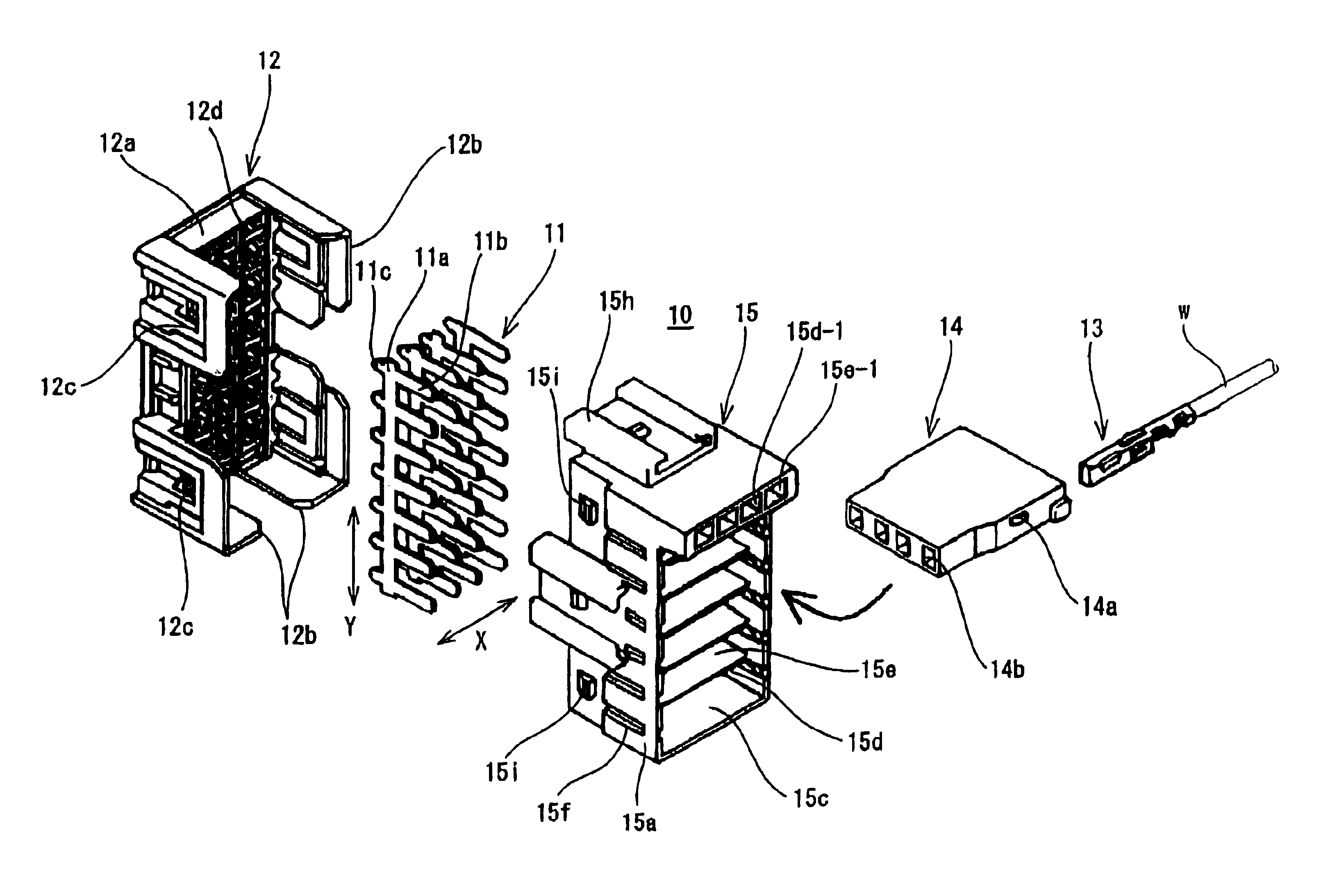
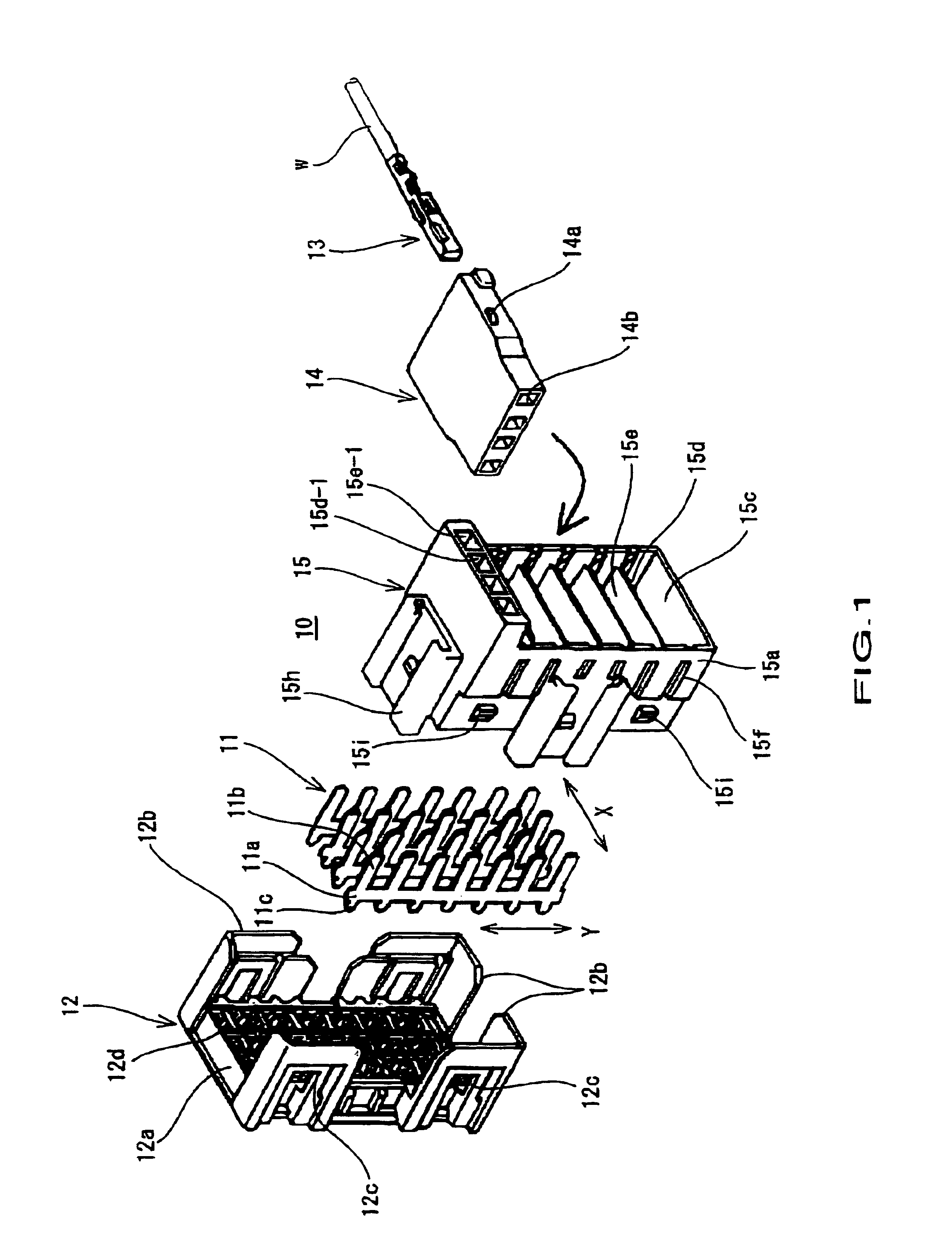
The following will describe various embodiments of the electrical connector box of the present invention with reference to the attached drawings. FIG. 1 illustrates connector box 10 which includes multiple bus bars 11 that are press fit into housing 12, block connectors 14 which contain female terminal connectors 13 to which wires w...


PUM


Abstract

An electrical connector box that provides multiple electrical circuit connections, simplifies alterations to circuit connection patterns, and allows for convenient continuity testing. The electrical connector box includes a housing and a holder that contains multiple vertically stacked receptacles. Multiple bus bars, of which multiple bus bar tabs are an integral part thereof, are press fit into the housing at uniform intervals, a block connector is inserted into each of vertically stacked receptacles in the holder, and the housing and holder are locked together during which the bus bar tabs in the housing are inserted into female terminal connectors held within the block connectors in the holder.

Description

BACKGROUND OF THE INVENTION1. Field of the InventionThe present invention relates to an automotive electrical connector box and a method of assembly of an automotive electrical connector box, and more particularly, to an electrical connector box that connects multiple circuits, is easy to assemble, and is configured for a simple continuity testing method.2. Description of Related ArtJapanese Kokai Patent S61-277180 describes a structure for a connector box which is illustrated in FIG. 5. The connector box includes a housing 1 having a closed end and into which joint bus bars 2 are fixedly installed with bus bar tabs 2a extending toward an open end of housing 1. When block connector 3 is inserted into housing 1, the female terminal connectors (to which wire ends are attached) held in block connector 3 join to tabs 2a, thus establishing an electrical connection between the female terminal connectors according to the configuration of bus bars 2.This type of conventional connector box r...

Claims


Application Information

Patent Timeline
Patent Type & Authority Patents(United States)
IPC IPC(8): H01R13/518H01R13/516H01R9/24H01R9/03H01R13/514H01R24/76H02G3/16
CPCH01R13/518H01R9/2408H01R2201/20
Inventor ODA, AKIHIRO
Owner SUMITOMO WIRING SYST LTD
Why Eureka
Try Eureka