
Tool side robotic safety interlock

a safety interlock and tool technology, applied in the field of robotics, can solve the problems of thwarting the safety benefit of the interlock, unable to design and implement a switch on the master unit that is operative with a variety of tools, and a deficient solution, and achieve the effect of improving the safety interlock

Inactive Publication Date: 2005-01-11
ATI INDAL AUTOMATION
View PDF8 Cites 50 Cited by
  • Summary
  • Abstract
  • Description
  • Claims
  • Application Information

AI Technical Summary

Problems solved by technology

Nevertheless, due to fear of software glitches, human error, and the like, it is desirable to interpose a hardware safety interlock into the decoupling circuit.
In practice, this has been found to be a deficient solution.
For example, it has been proven difficult to design and implement a switch on the master unit that is operative with a variety of tools, due to the different geometries that each tool presents.
It has been discovered that in many applications, personnel simply connect a short-circuit connector to the contacts, thus thwarting the safety benefit of the interlock.
However, such a relocation introduces a problem: when the master and tool units are decoupled, as described above, the default position of the coupler is the coupled position.
Yet the circuit to actuate the coupler is broken, and, regardless of the position of the tool-mounted switch, the circuit cannot be closed until the master and tool units are mated together and the utility contacts complete the circuit from the controller in the master unit, through the switch mounted on the tool, back to the coupler in the master unit.

Method used


Image

  • Tool side robotic safety interlock
  • Tool side robotic safety interlock
  • Tool side robotic safety interlock

Examples


Embodiment Construction

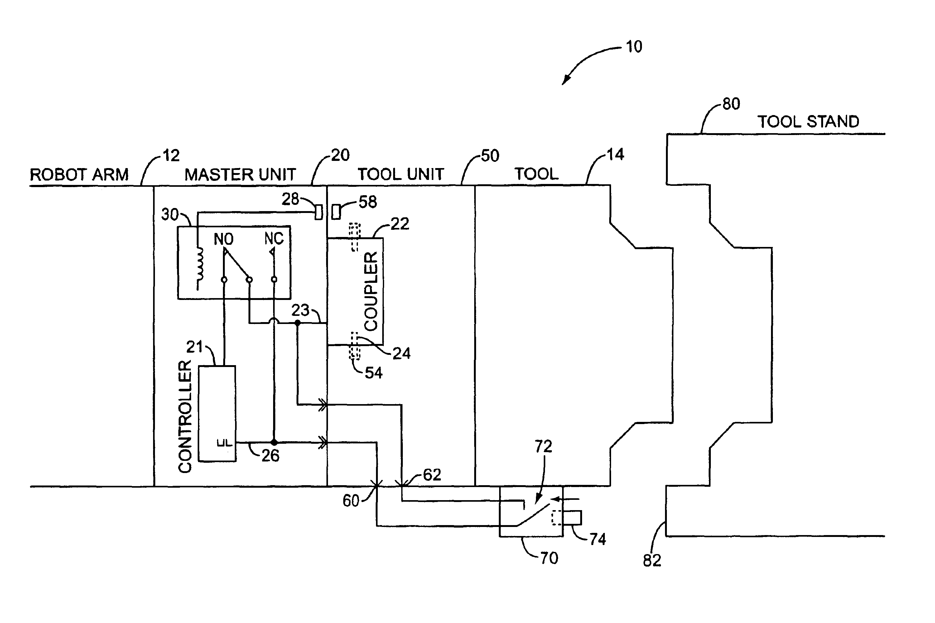
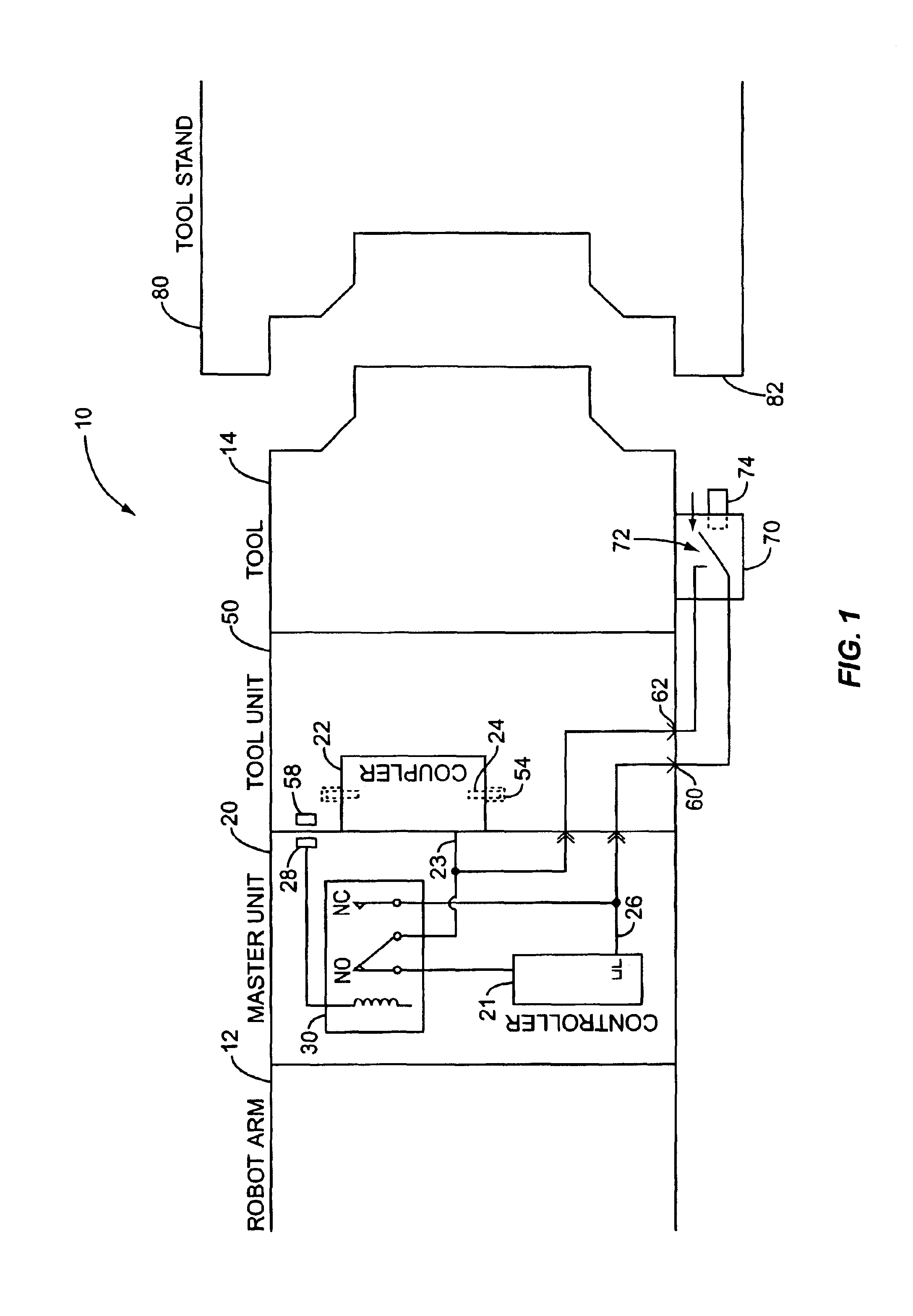
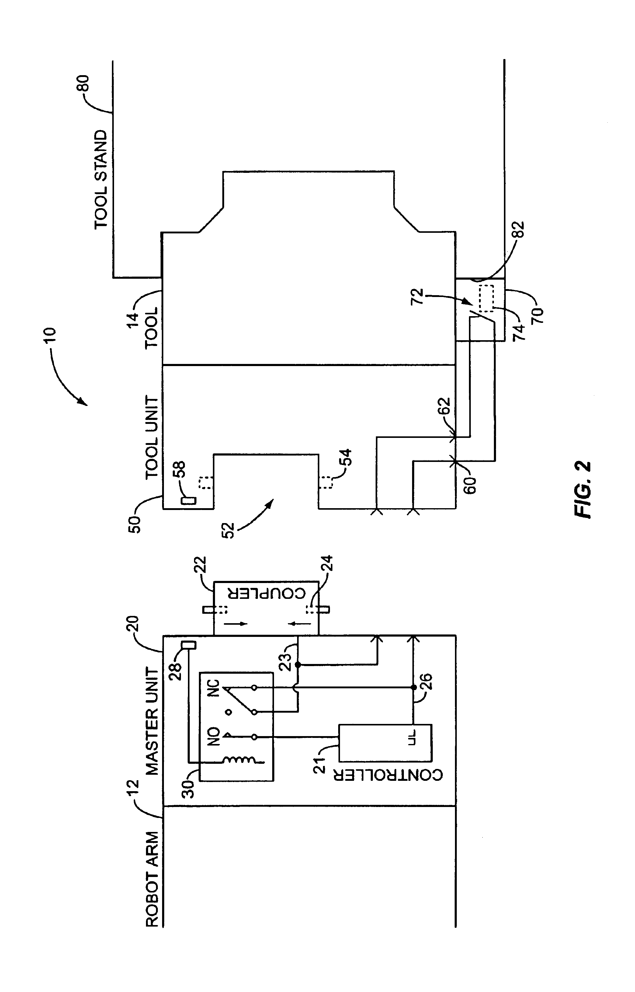
The present invention relates to a robotic tool changer with an inventive tool safety interlock circuit. FIGS. 1 and 2 both depict, in functional block diagram form, one implementation of the tool changer of the present invention, in different configurations. Like parts are numbered consistently between the figures, and both figures should be referred throughout the following discussion. It should be noted that the tool safety interlock depicted in FIGS. 1 and 2 comprises electrical circuits. The present invention is not, however, limited to this embodiment, and, as described below, may be implemented in a variety of ways.

The tool changer according to the present invention, indicated generally by the numeral 10, comprises master unit 20 and tool unit 50. The tool changer 10 provides a standard interface for physically coupling a robot arm 12 with a robotic tool 14. The tool changer 10 selectively physically couples the master unit 20 to the tool unit 50, and additionally supplies va...


PUM


Abstract

A robotic tool changer with an improved safety interlock includes a master unit, a tool unit, and a coupler movable between coupled and decoupled positions and operative to couple the master and tool units. A circuit for actuating the coupler is associated with the tool unit, for connection to an interlock that closes when the tool is safely parked in a tool stand. The circuit enables the coupler to assume the decoupled position when the master and tool units are coupled and the circuit is closed. The robotic tool changer additionally includes a circuit operative to enable the coupler to assume the decoupled position when the master unit is decoupled from the tool unit.

Description

BACKGROUND OF THE INVENTIONThe present invention relates generally to the field of robotics and specifically to a safety interlock provided on the tool side of a robotic tool changer.Industrial robots have become an indispensable part of modem manufacturing. Whether transferring semiconductor wafers from one process chamber to another in a cleanroom or cutting and welding steel on the floor of an automobile manufacturing plant, robots perform many manufacturing tasks tirelessly, in hostile environments, and with high precision and repeatability.In many robotic manufacturing applications, it is cost-effective to utilize a relatively generic robot to accomplish a variety of tasks. For example, in an automotive manufacturing application, a robot may be utilized to cut, grind, or otherwise shape metal parts during one production run, and perform a variety of spot welding tasks in another. Different welding tool geometries may be advantageously mated to a particular robot to perform weld...

Claims


Application Information

Patent Timeline
Patent Type & Authority Patents(United States)
IPC IPC(8): B23Q3/155B25J19/06B25J15/04
CPCB23Q3/15546B25J15/04B25J15/0491B25J19/06Y10T483/17Y10T483/10Y10T483/13Y10T483/136Y10S483/901
Inventor PERRY, DWAYNEHEAVNER, RICHARD
Owner ATI INDAL AUTOMATION
Learn More