Hall-effect current detector

a current detector and current path technology, applied in voltage/current isolation, instruments, galvano-magnetic devices, etc., can solve the problems of low productivity per unit of effort, prone to fluctuation of positional relationship between current-path conductor and hall generator, and difficulty in ensuring consistently high sensitivity and reliability for all models manufactured. to achieve the effect of reducing electrostatic nois

Inactive Publication Date: 2005-01-11
SANKEN ELECTRIC CO LTD
View PDF8 Cites 79 Cited by
  • Summary
  • Abstract
  • Description
  • Claims
  • Application Information

AI Technical Summary

Benefits of technology

That surface of the metal-made mounting plate which has the Hall generator attached thereto may be directed either toward, or away from, the current-path conductor. With the Hall generator placed between mounting plate and current-path conductor, the mounting plate will most effectively serve as a noise shield. When itself disposed between Hall generator and current-path conductor, on the other hand, the mounting plate will function to reduce electrostatic noise from the conductor.
Preferably, for ease of fabrication and assemblage, the current detector may be constituted of a Hall generator assembly and a current-path conductor assembly. The Hall generator assembly may comprise the Hall generator, and a plastic encapsulation enveloping bo

Problems solved by technology

The integral construction, from an early stage of manufacture, of the current-path conductor and the Hall generator is objectionable because the complete device has to be discarded for a defect associated with either the current-path conductor and the Hall generator, resulting in low productivity per unit of effort

Method used


Image

  • Hall-effect current detector
  • Hall-effect current detector
  • Hall-effect current detector

Examples


embodiment

of FIG. 21

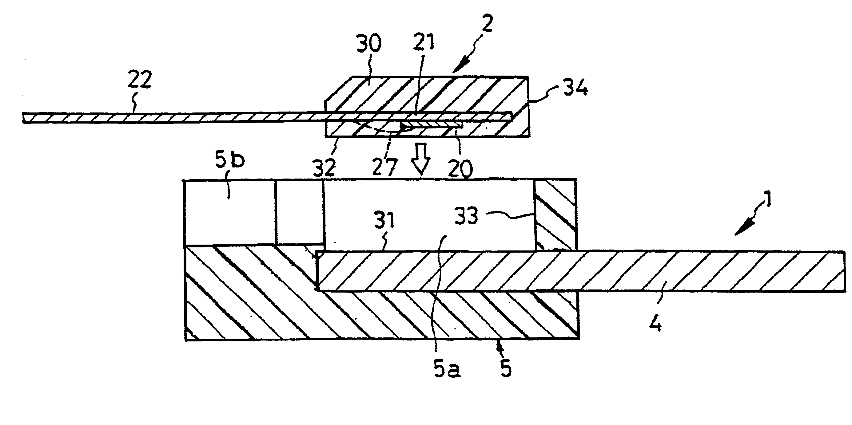
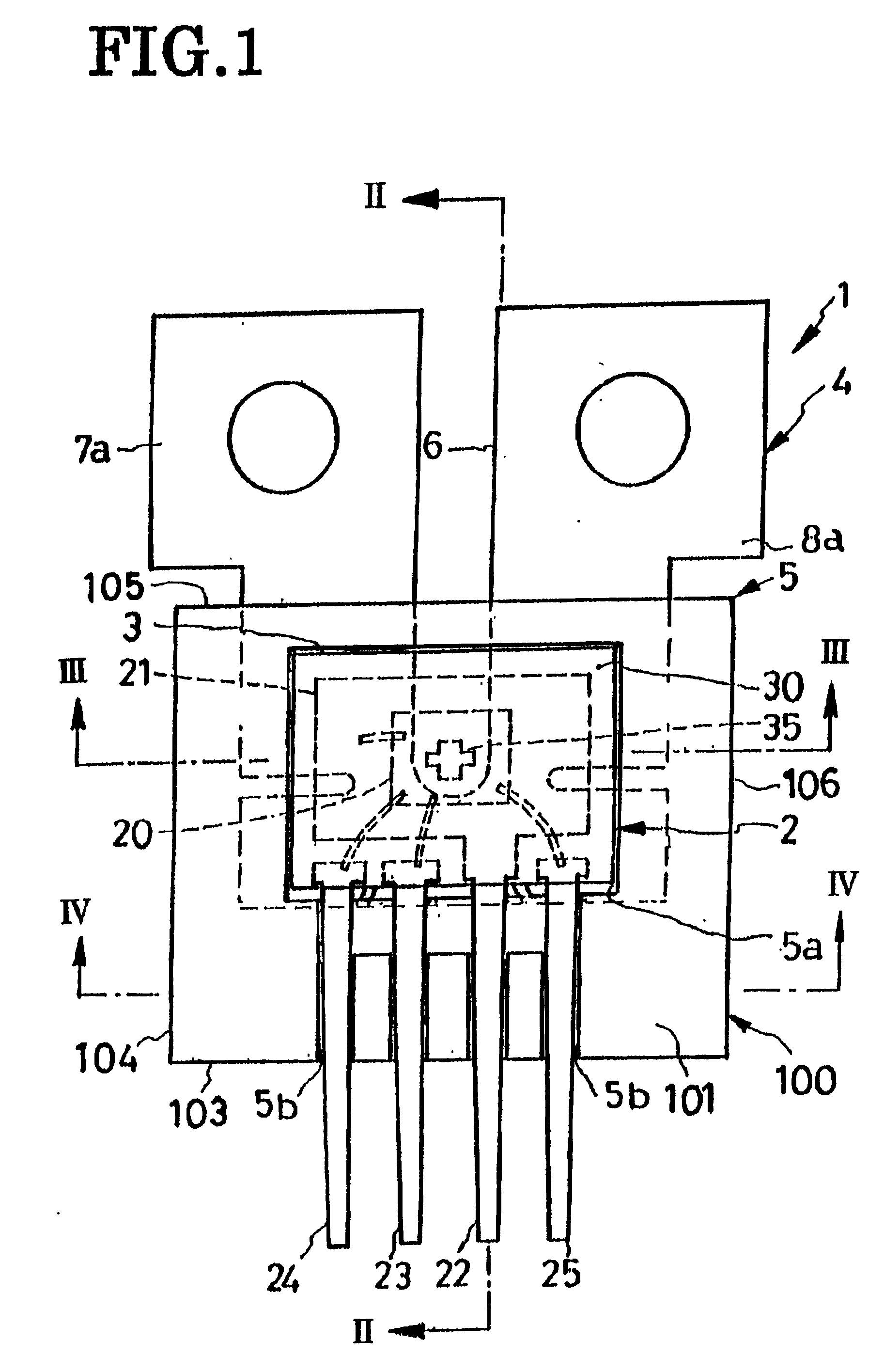
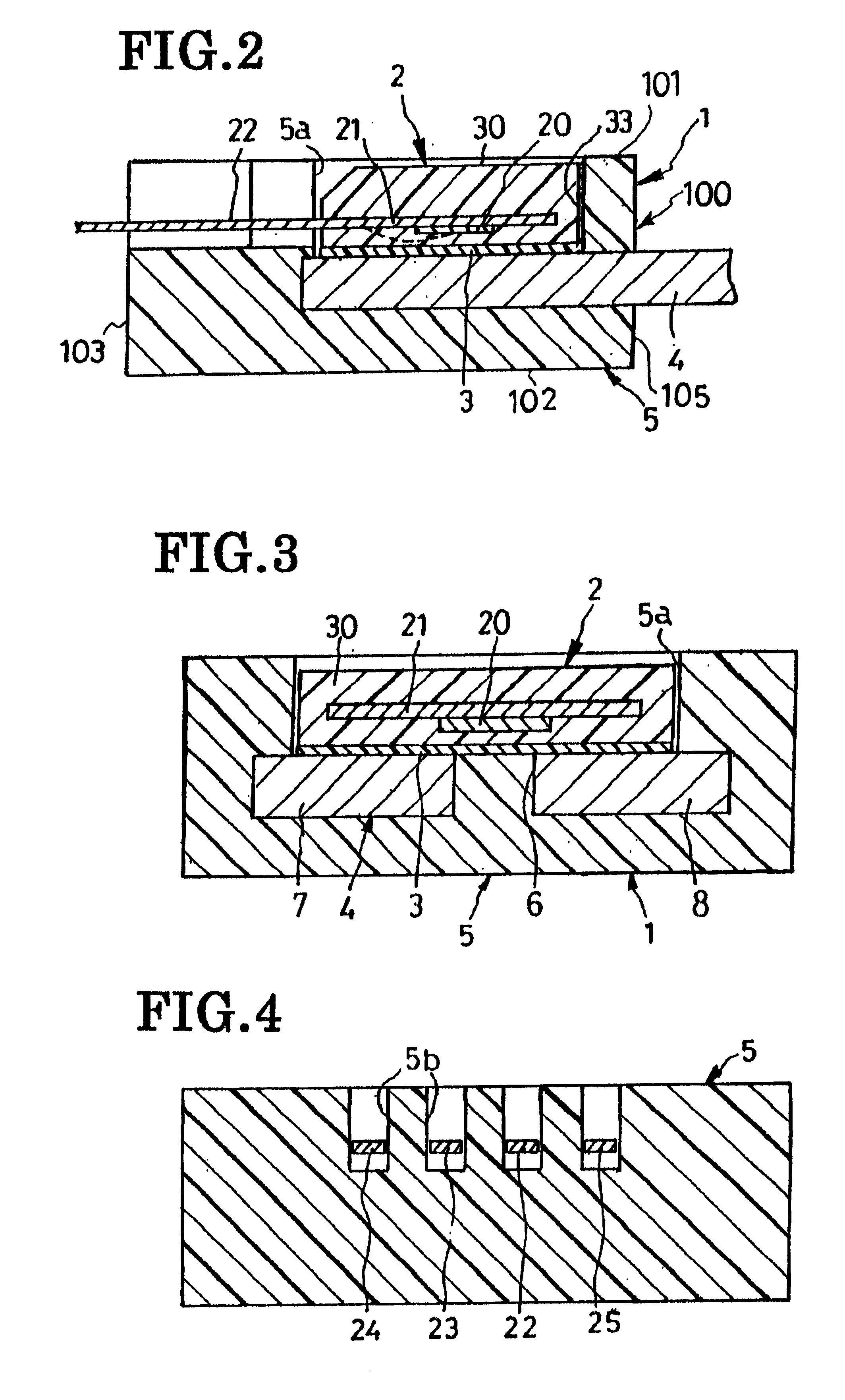
The FIG. 21 current detector is a combination of a modified current-path conductor assembly 1a and the original Hall generator assembly 2 of the FIGS. 1-14 construction. The modified current-path conductor assembly 1a comprises a modified sheet-metal current-path conductor 4b and a modified conductor holder 5″. The current-path conductor 4b has a pair of terminal portions 7a and 8a which are bent right-angularly in opposite directions from the rest of the parallel limbs of the conductor. The conductor holder 5″ integrally envelops all but the terminal portions 7a and 8a of the current-path conductor 4b, with these terminal portions projecting in opposite directions from the side surfaces 104 and 106 of the conductor holder 5″, or of the casing 100a constituted of the conductor holder 5″ and Hall generator encapsulation 30 bonded together. The four leads 22-25 of the Hall generator assembly 2 all extend from the side surface 103 of the casing 100a, as in the FIGS. 1-14 embo...


PUM


Abstract

A current detector comprising a current-path conductor assembly and a Hall generator assembly. The current-path conductor assembly includes a sheet-metal current-path conductor and a plastic conductor holder molded in one piece therewith. The Hall generator assembly includes a Hall generator in the form of a semiconductor chip mounted to a metal-made mounting plate, a set of leads electrically connected to the Hall generator, and a plastic encapsulation enveloping the Hall generator and parts of the leads. The Hall generator assembly and the current-path conductor assembly are combined by bonding together the encapsulation of the Hall generator assembly and the conductor holder of the current-path conductor assembly. The conductor holder and the encapsulation are shaped in interfitting relationship to each other, so that when they are united, the Hall generator is positioned to generate a Hall voltage in response to a magnetic field due to the current flowing through the current-path conductor.

Description

BACKGROUND OF THE INVENTIONThis invention relates to a current detector for detection or measurement of electric current flowing in an electric circuit, and more specifically to such a detector incorporating a Hall-effect device more generally known also as Hall generator.The Hall generator is built upon the familiar Hall effect to develop a voltage, known as Hall voltage, in proportion to the strength of the magnetic field applied. The Hall generator therefore lends itself to use as a magnetism detector. Additionally, positioned contiguous to a path of electric current, the Hall generator will put out a voltage indicative of the magnitude of the current by being acted upon by the magnetic field appearing in proportion to the current magnitude. The closer the Hall generator is positioned to the current path, the higher will be its sensitivity of current detection.The instant applicant proposed in Japanese Unexamined Patent Publication No. 2000-174357 a current detector employing a H...

Claims


Application Information

Patent Timeline
IPC IPC(8): G01R15/14G01R15/20G01R33/06G01R33/07
CPCG01R33/07G01R15/202H01L2224/48091H01L2224/48247H01L2224/48257H01L2924/181H01L2924/00014H01L2924/00012
Inventor GOTO, HIROKAZUHASEGAWA, AKIRAOHTSUKA, KOJIKATO, TAKASHI
Owner SANKEN ELECTRIC CO LTD
Why Eureka
Try Eureka