Capacitance type sensor

a technology of capacitive sensors and sensors, applied in the direction of instruments, pulse techniques, apparatus for force/torque/work measurement, etc., can solve the problem of being unsuitable for use as a device having a switch function for switching between two different states

Inactive Publication Date: 2005-01-11
NITTA CORP
View PDF7 Cites 22 Cited by
  • Summary
  • Abstract
  • Description
  • Claims
  • Application Information

AI Technical Summary

Benefits of technology

In the capacitance type sensor of the present invention, said detective member is preferably covered with a transparent insulating member. By this construction, in case of the detective member made of a metal, the surface of the detective member can be prevented from being exposed to ai

Problems solved by technology

However, though the capacitance type sensor 510 illustrated in FIGS. 30 and 31 is suitable for use as a device (force sensor) for recognizing the intensity of the force when the o

Method used


Image

  • Capacitance type sensor
  • Capacitance type sensor
  • Capacitance type sensor

Examples


second embodiment

Next, the present invention will be described with reference to drawings.

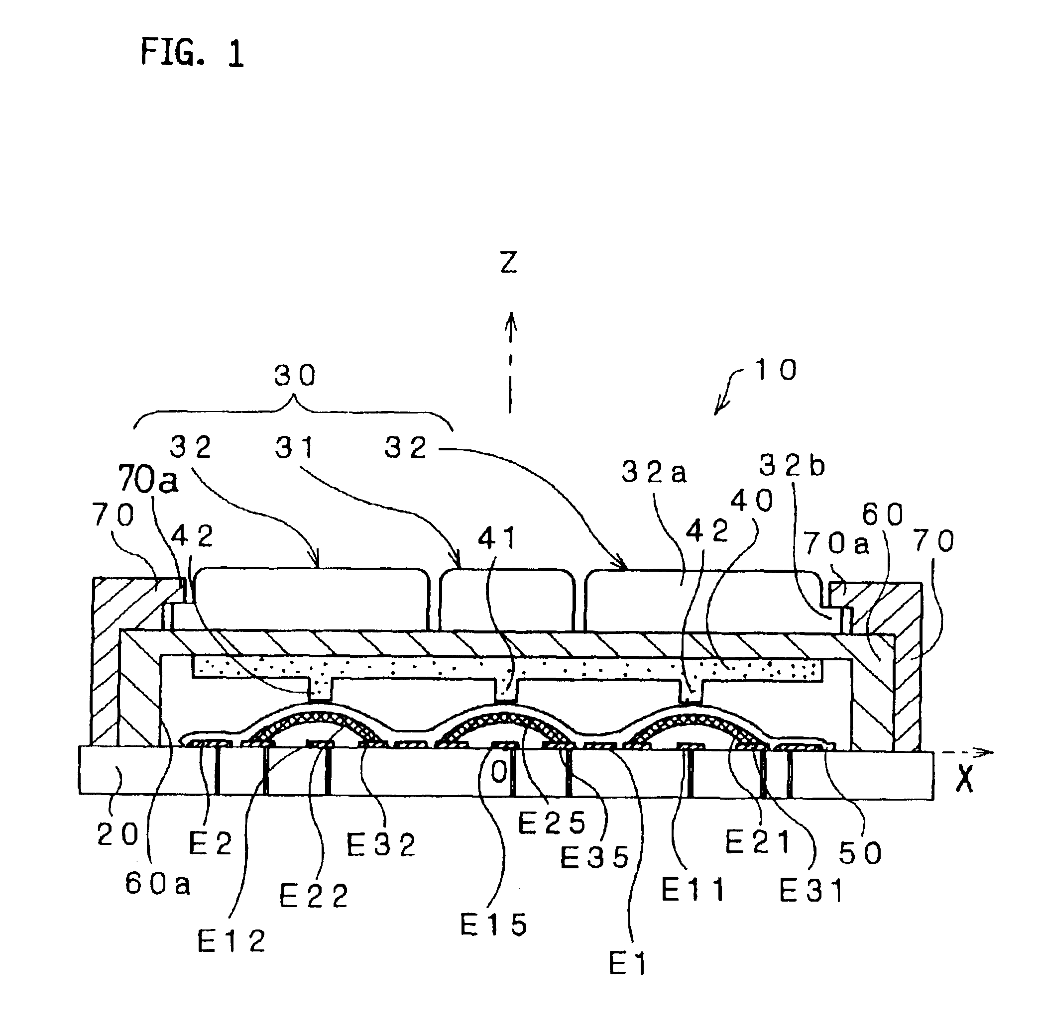
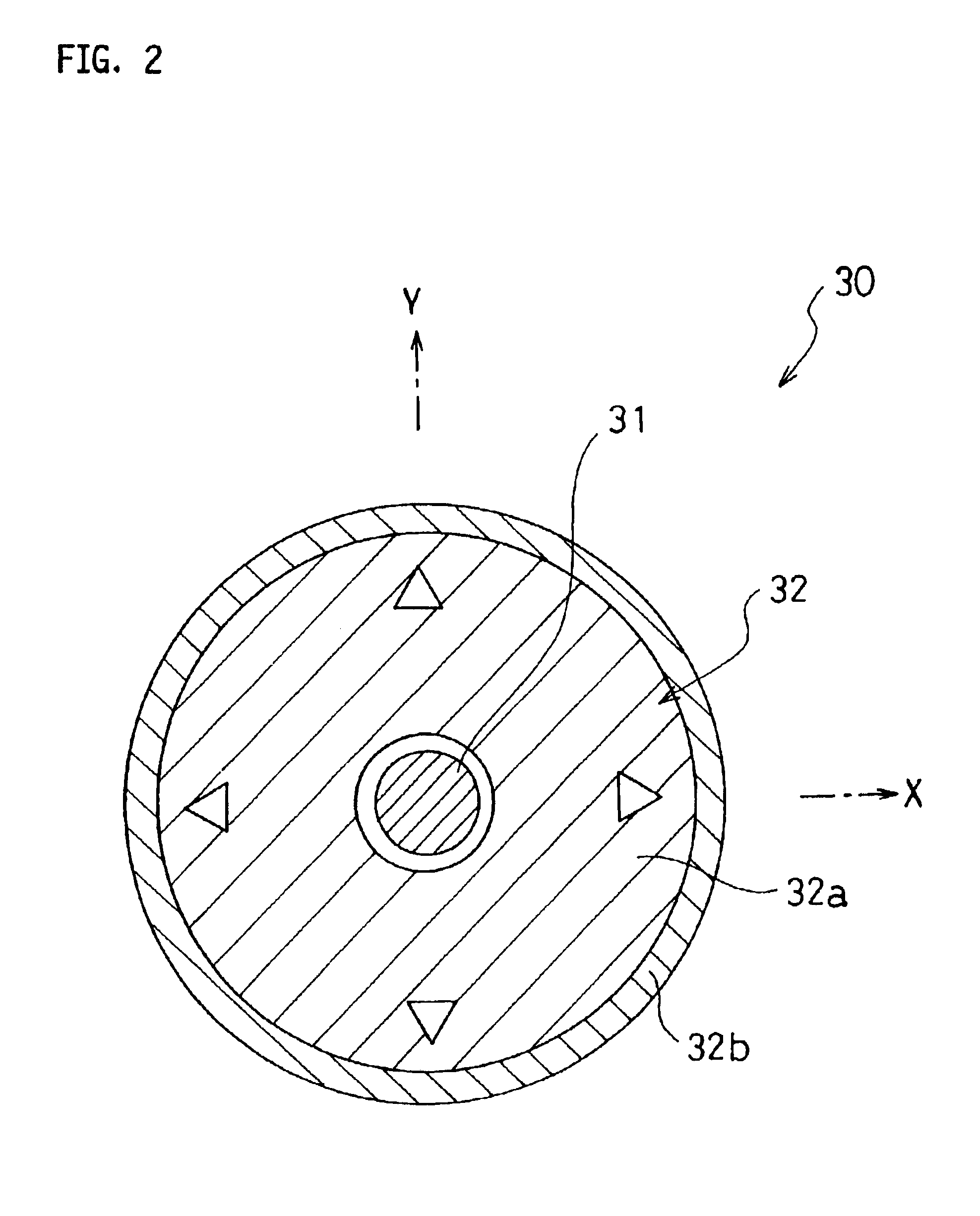
FIG. 13 is a schematic sectional side view of a capacitance type sensor according to another embodiment of the present invention. FIG. 14 is an upper view of a detective member of the capacitance type sensor of FIG. 13. FIG. 15 is a view illustrating an arrangement of electrodes formed on, a substrate of the capacitance type sensor of FIG. 13. FIG. 16 is an upper view of a letter print member of the capacitance type sensor of FIG. 13.

The capacitance type sensor 110 includes a substrate 120, an operation detective member 130 to which a force is externally applied by being operated by a person or the like, a displacement electrode 140, capacitance element electrodes E101 to E104 formed on the substrate 120, movable switch electrodes E121 to E124 (FIG. 13 illustrates only E121 and E122) each having a dome shape, fixed switch electrodes E111 to E114 disposed inside the movable switch electrodes E121 to E124, refere...

third embodiment

Next, the present invention will be described with reference to drawings.

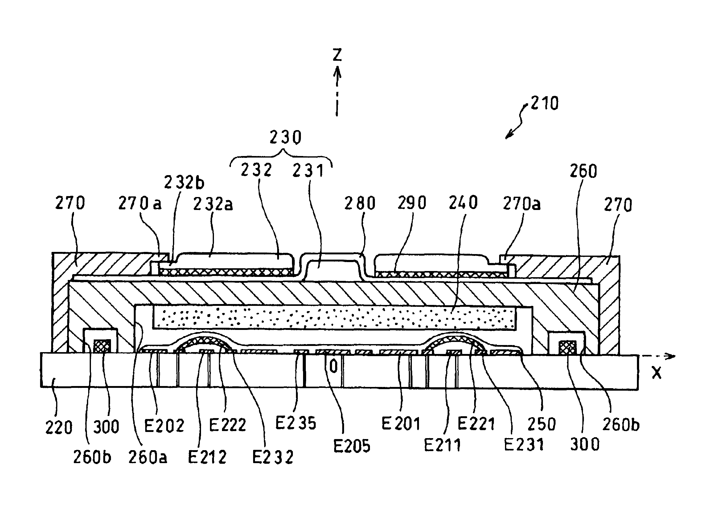
FIG. 24 is a schematic sectional view of a capacitance type sensor according to the third embodiment of the present invention. FIG. 25 is an upper view of a detective member of the capacitance type sensor of FIG. 24. FIG. 26 is a view illustrating an arrangement of electrodes formed on a substrate of the capacitance type sensor of FIG. 24. FIG. 27 is an upper view of a letter print member of the capacitance type sensor of FIG. 24.

The capacitance type sensor 210 includes a substrate 220, a detective member 230 made up of a central button 231 and a side button 232 to each of which a force is externally applied by being operated by a person or the like, a displacement electrode 240, capacitance element electrodes E201 to E205 formed on the substrate 220, movable switch electrodes E221 to E224 (FIG. 24 illustrates only E221 and E222) each having a dome shape, fixed switch electrodes E211 to E214 (FIG. 24 illustrate...


PUM


Abstract

A capacitance element electrode (E1) and a reference electrode (E31) are formed on a substrate (20) so as to be opposite to a displacement electrode (40). A dome-shaped movable switch electrode (E21) is disposed so as to be in contact with the reference electrode (E31) and at a distance from a fixed switch electrode (E11) formed inside the reference electrode (E31), and to cover the fixed switch electrode (E11). When an operation is applied to a detective member (30) and a portion of the movable switch electrode (E21) in the vicinity of its top is displaced to be brought into contact with fixed switch electrode (E11), a switch is turned ON. On the other hand, from a change in capacitance value of a capacitance element (C1) formed between the displacement electrode (40) and the capacitance element electrode (E1), the intensity of the force to the detective member (30) can be recognized.

Description

TECHNICAL FIELDThe present invention relates to capacitance type sensors, in particular, suitably used for inputting operations in multidimensional directions and also usable as devices having switch functions.BACKGROUND ARTA capacitance type sensor is generally used as a device for converting into an electric signal the intensity and direction of a force applied by an operator. For example, as an input device for a game machine used is a device incorporated as a capacitance type force sensor (so-called joy stick) for inputting operations in multidimensional directions.Using the capacitance type sensor, an operation quantity with a predetermined dynamic range can be input as the intensity of a force applied by the operator. Such a sensor may be used in the form of a two-dimensional or three-dimensional force sensor capable of detecting each directional component divided from the applied force. In particular, a capacitance type sensor in which a capacitance element is made up of two ...

Claims


Application Information

Patent Timeline
IPC IPC(8): G01L5/16G06F3/033H01H25/04H01H25/00G06F3/0338G06F3/044H03K17/98
CPCG01L5/165G06F3/0338H03K17/98G06F3/044H01H25/008H01H25/041G06F3/0446
Inventor MORIMOTO, HIDEO
Owner NITTA CORP
Why Eureka
Try Eureka