Integrated tape

Inactive Publication Date: 2005-01-11
S C POWER SYST
View PDF52 Cites 1 Cited by
  • Summary
  • Abstract
  • Description
  • Claims
  • Application Information

AI Technical Summary

Benefits of technology

The available developmental designs of superconducting cables use conductors comprising superconducting tapes helically applied to a tubular former. This former also serves as a coolant duct. Economic considerations dictate that the energy transmission capacity of a superconducting cable be large. This arises from that fact that use of such cables at modest current levels often results in refrigeration losses which exceed the losses due to the resistance of a conventional copper conductor of similar capacity. Moreover, the formers and the cooling systems are designed to perform with three or four layers of tapes wound onto the former. Use of tapes according to the present invention, however, are anticipated to allow comparable capacity to be achieved with only one or two layers of tapes, permitting the capacities of tapes to be used substantially more efficiently.

Problems solved by technology

Availability issues may necessitate the latter.
In practice, it is generally geometrical constraints on packing equal round components into approximately round assemblies that limit the number if filaments.

Method used


Image

  • Integrated tape
  • Integrated tape
  • Integrated tape

Examples


Embodiment Construction

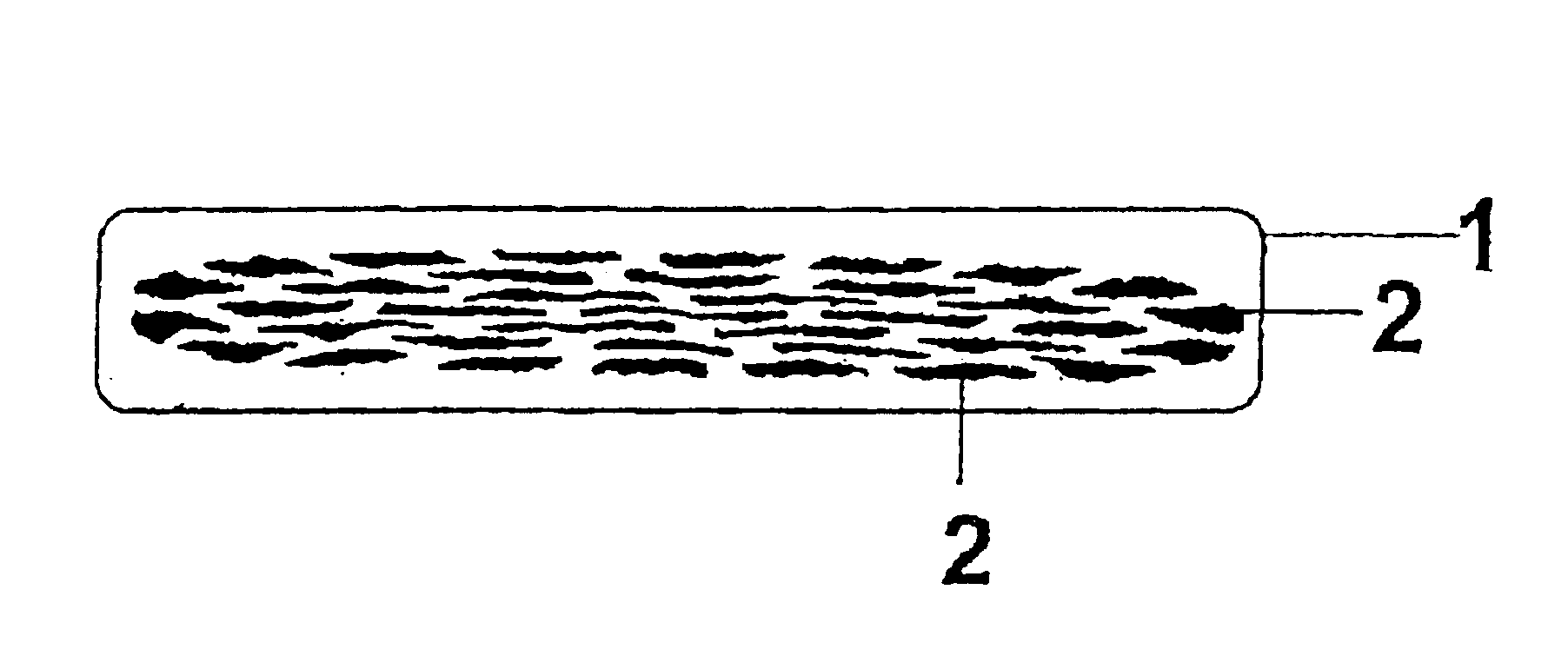
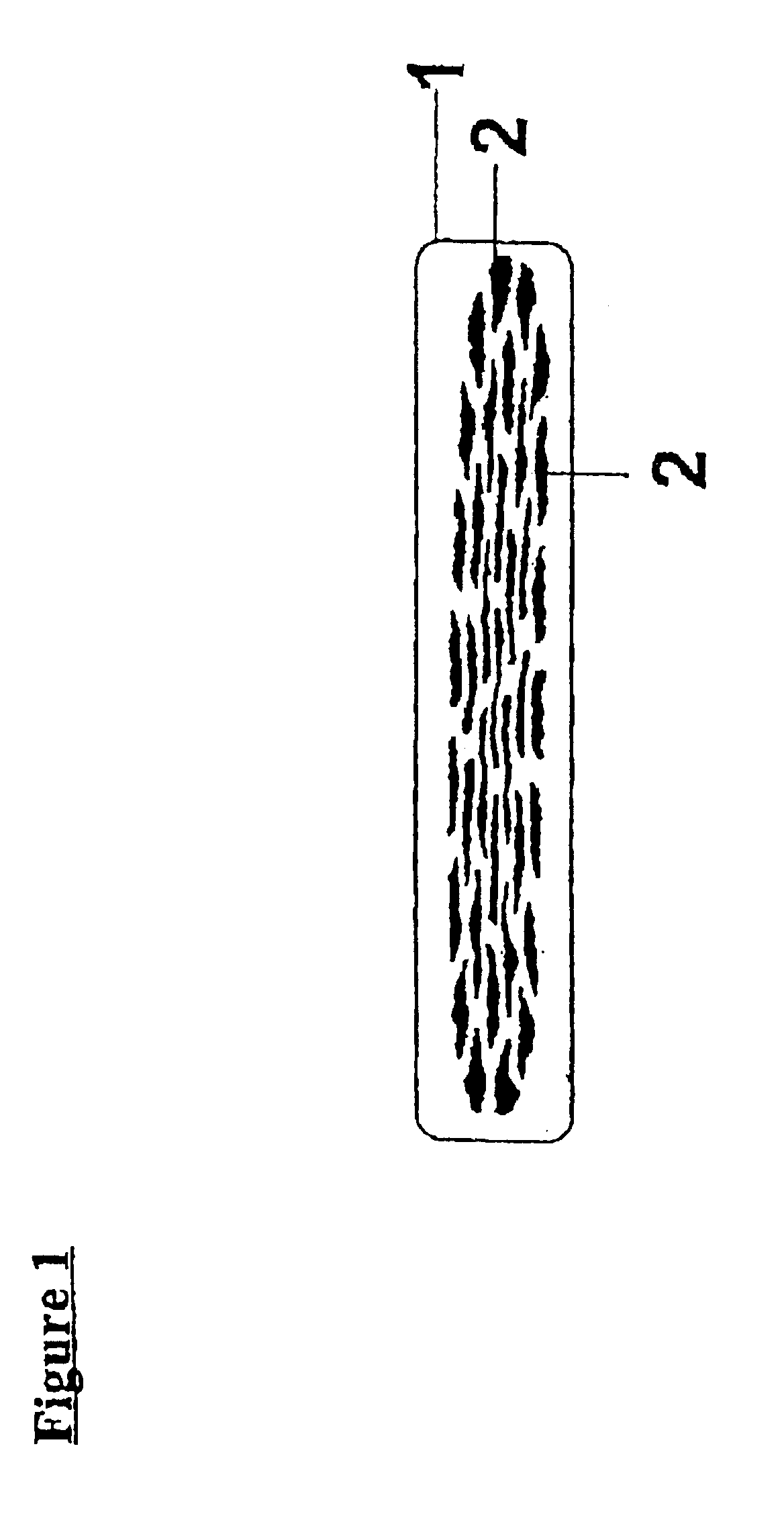
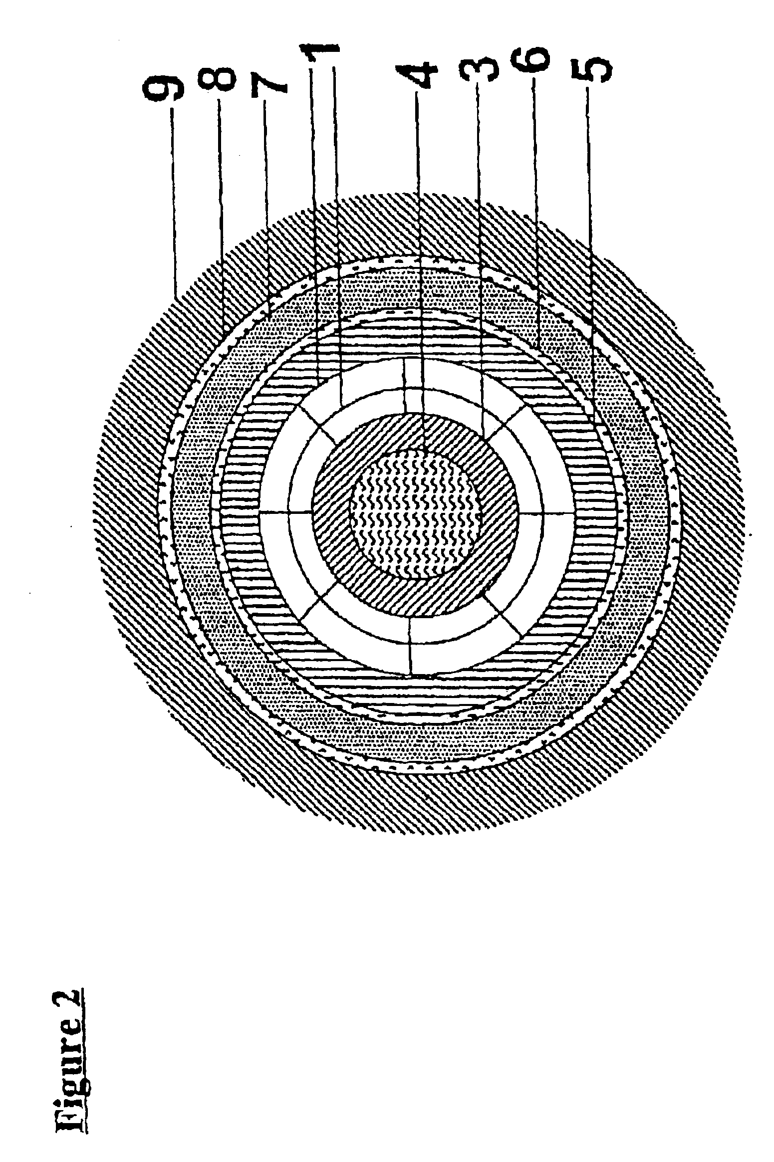
In the manufacture of the superconducting tape of this example, BSCCO-2223 precursor powder is first filled into a pure silver tube. For the example where the number of filaments included is 75, the silver tube has internal and external diameters of 1.9 and 14.1 mm respectively and degassed by placing in a cool oven (in air), heating to bout 830° C. and holding for 5 hours. After cooling, the assembly is drawn to a diameter of 1.11 mm in a series of stages with a reduction in the area of about 15% at each stage, annealing at 500° C. after 16 steps and thereafter every 3 subsequent steps. Seventy-five cut lengths of the drawn assembly can now be arranged (in five concentric layers of 3, 9, 15, 21, 27) inside another length of the same silver tube. The resulting assembly is further drawn to a diameter of 1.31, 1.54 or 2.31 mm, again in steps of about 15% reduction in area.

For the example where the number of filaments is 127, the precursor powder is filled into a pure silver tube with ...


PUM

PropertyMeasurementUnit
Thicknessaaaaaaaaaa
Thicknessaaaaaaaaaa
Thicknessaaaaaaaaaa

Abstract

Production of a superconducting tape of the powder-in-tube type comprising multiple filaments (1) of superconducting material embedded in a silver matrix (2) having the properties of a filament thickness of less than about 40 μm and an overall tape thickness in the range from about 0.45 mm to 1.20 mm. A superconducting power cable including a tubular copper former (3) defining a cooling duct (4) about which superconducting tape is helically laid in two layers of either the same or opposite hand. The cable further includes thermal insulation (5), an electrical screen (6), electrical insulation (7), a further electrical screen (8) and containment (9).

Description

FIELD OF THE INVENTIONThe present invention relates to a superconducting tape and in particular to a superconducting tape of the powder-in-tube type.BACKGROUND OF THE INVENTIONThe invention has been developed primarily for carrying alternating current and will be described hereinafter with reference to that application. It will be appreciated however that the invention is not limited to that particular field of use and is also suitable for carrying DC current.It is known to produce a superconducting wire by filling a tube of silver or silver alloy with particulate high-temperature ceramic superconductor. By way of example, it is known to use a superconductor selected from the class known as “BSCCO” superconductors. Of these, the subgroup known as BSCCO-2223 is most preferred.Once the superconductor is placed in the tube further process steps occur. More particularly, the tube is rolled to reduce its cross-section to compact it. Further rolling is carried out to eventually flatten th...

Claims


Application Information

Patent Timeline
IPC IPC(8): H01L39/14H01B12/10H01B13/00H01L39/24
CPCH01L39/143H01L39/248Y10T428/2931Y10T428/24132Y10S428/93Y10T428/249927H10N60/203H10N60/0801
Inventor DARMANN, FRANCIS ANTHONY
Owner S C POWER SYST
Why Eureka
Try Eureka