
Fuel supply arrangement for a motorcycle engine

a technology for motorcycle engines and fuel supply, which is applied in the direction of air cleaner and silencer combination, electric control, cycle equipment, etc., can solve the problems of increasing the amount of time needed to perform certain routine maintenance procedures on the engine, reducing the performance of the engine, and adding to the weight of the motorcycl

Inactive Publication Date: 2005-01-18
YAMAHA MOTOR CO LTD
View PDF11 Cites 20 Cited by
  • Summary
  • Abstract
  • Description
  • Claims
  • Application Information

AI Technical Summary

Problems solved by technology

Significantly, the stays, or arm members, that extend from the inlet duct and of the support frame to support the fuel injector interfere with a flow of air entering the intake passage through the inlet duct.
Accordingly, the resistance to a flow of intake air into the engine is increased, which results in a reduction in the performance of the engine.
Furthermore, the inlet duct, support frame, and secondary fuel injector must be disassembled in order to remove the air cleaner box and / or the throttle body, thus increasing the amount of time needed to perform certain routine maintenance procedures to the engine.
Furthermore, the support frame adds to the weight of the motorcycle and also increases the manufacturing cost.

Method used


Image

  • Fuel supply arrangement for a motorcycle engine
  • Fuel supply arrangement for a motorcycle engine
  • Fuel supply arrangement for a motorcycle engine

Examples


Embodiment Construction

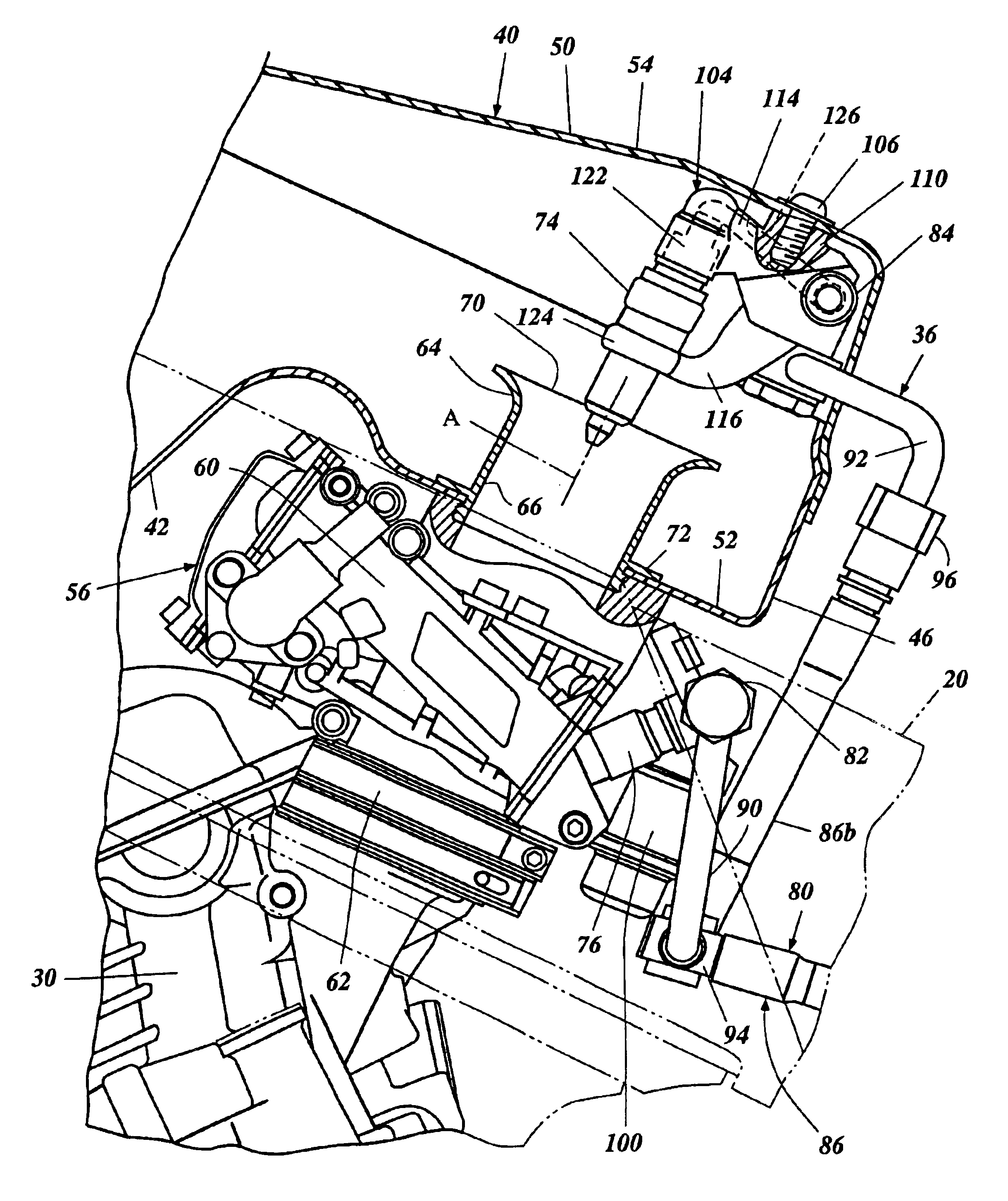
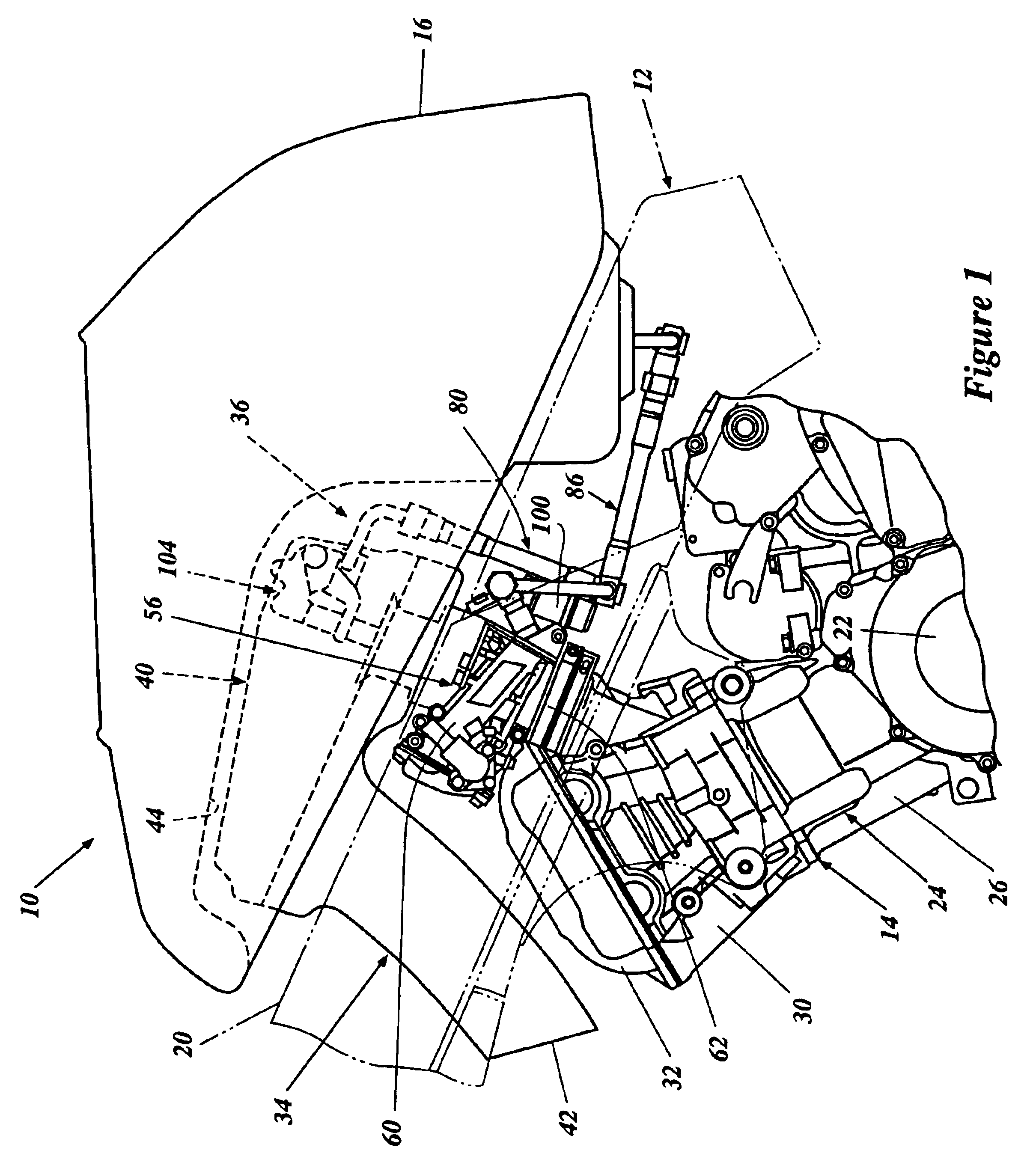
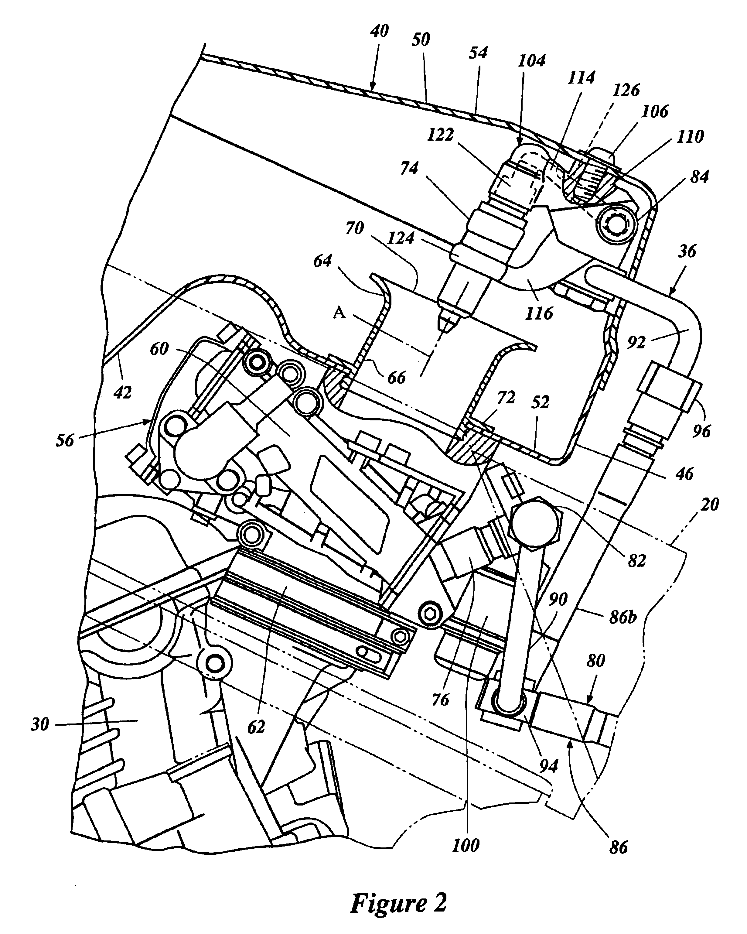
FIGS. 1 through 3 illustrate a motorcycle, generally referred to by the reference numeral 10, incorporating a preferred embodiment of the present fuel delivery system. Preferably, the preferred embodiment includes a fuel injector mounting arrangement that provides for less interruption of intake air flow than prior fuel injector supports. Furthermore, such a preferred mounting arrangement provides for ease of dissassembly of the air box. In addition, preferably, the mounting arrangement does not substantially increase the size of the air box or the overall weight of the fuel delivery system. In addition, preferably, the mounting arrangement does not significantly increase manufacturing costs.

Although described in the context of use on a motorcycle 10, the present fuel delivery system may also be utilized in connection with a number of other types of vehicles, such as all terrain vehicles, snowmobiles, outboard motors and personal watercraft, for example. The motorcycle 10 and fuel d...


PUM


Abstract

A fuel delivery system for a motorcycle including an engine having at least one combustion chamber. The fuel delivery system includes a fuel injector configured to deliver a fuel charge to an intake passage of the engine. The motorcycle further includes an air box defining an interior space, or plenum chamber. An inlet duct defines at least a portion of the intake passage and further defines an axis. The inlet duct also defines an opening to the intake passage disposed within the plenum chamber. A spray axis of the fuel injector is oriented parallel to the axis of the inlet duct and the fuel injector is supported by the air box.

Description

RELATED APPLICATIONSThis application is related to, and claims priority from, Japanese patent application No. 2002-220855, filed Jul. 30, 2002, the entirety of which is expressly incorporated by reference herein.BACKGROUND OF THE INVENTION1. Field of the InventionThe present invention relates generally to a fuel delivery system for an engine, and more particularly, to a fuel injector mounting arrangement.2. Description of the Related ArtMotorcycles are often equipped with engines employing a fuel-injection-type fuel delivery system to deliver fuel to a combustion chamber of the engine. Such a fuel delivery system, especially in high performance motorcycles, may include a fuel injector positioned adjacent an opening of an intake passage of the engine. The fuel injector is configured to deliver a fuel charge to the intake passage and may be used in combination with an additional fuel injector positioned downstream from the intake passage opening or, alternatively, positioned in direct...

Claims


Application Information

Patent Timeline
IPC IPC(8): F02M69/30F02M69/46F02M61/00F02M61/14F02M69/32F02M69/04F02M35/14B62J35/00F02D41/38F02M35/04F02M35/10F02M69/00F02M69/28
CPCF02M35/10032F02M35/10039F02M35/10098F02M35/10177F02M35/10216F02M35/112F02M69/465F02M35/162F02M61/145F02M69/043F02M69/044F02M69/28F02M69/325F02M35/14
Inventor MATSUDA, TAKESHIMUROO, SAKIO
Owner YAMAHA MOTOR CO LTD
Learn More