Vehicle fold-out ramp

a technology for vehicles and ramps, applied in the field of wheelchair lifts, can solve the problems of requiring more torque about the hinges, requiring longer ramps, and many of such systems cannot be moved manually, and achieve the effect of reducing the for

Inactive Publication Date: 2005-01-18
ELEVATOR U DIV OF HOGAN MFG
View PDF24 Cites 65 Cited by
  • Summary
  • Abstract
  • Description
  • Claims
  • Application Information

AI Technical Summary

Benefits of technology

In accordance with the present invention, a wheelchair ramp assembly is provided. The wheelchair ramp assembly includes a frame attachable to a vehicle having a floor, a platform coupled to a portion of the frame, a ramp having a weight, and a reciprocating mechanism disposed between the ramp and platform. The reciprocating mechan

Problems solved by technology

Fold-out ramps on vehicles confront a variety of technical problems.
Longer ramps are, however, heavier and require more torque about the hinge to be reciprocated between deployed and stowed positions.
Many of such systems cannot be moved manually in the event of failure of the power source unless the drive mechanism is first disengaged.
Some existing fold-out ramps can be deployed or stowed manually, but they are difficult to operate because one must first overcome the resistan

Method used


Image

  • Vehicle fold-out ramp
  • Vehicle fold-out ramp
  • Vehicle fold-out ramp

Examples


third embodiment

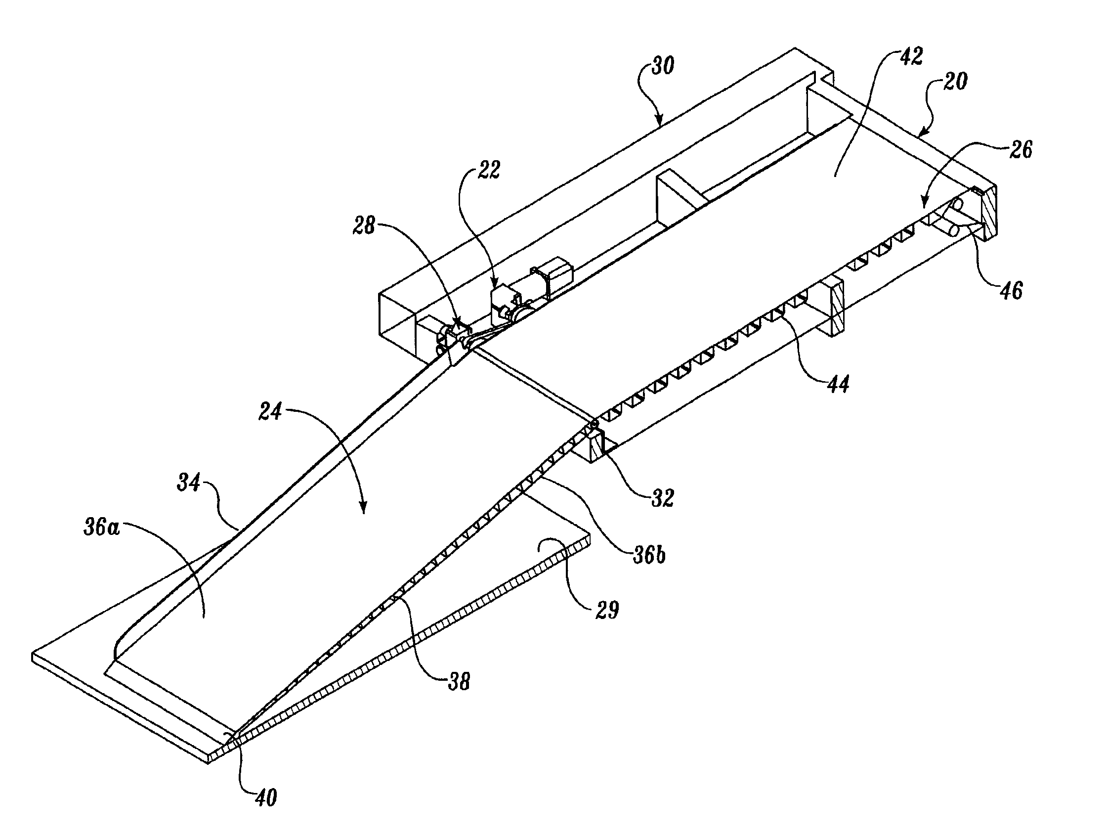
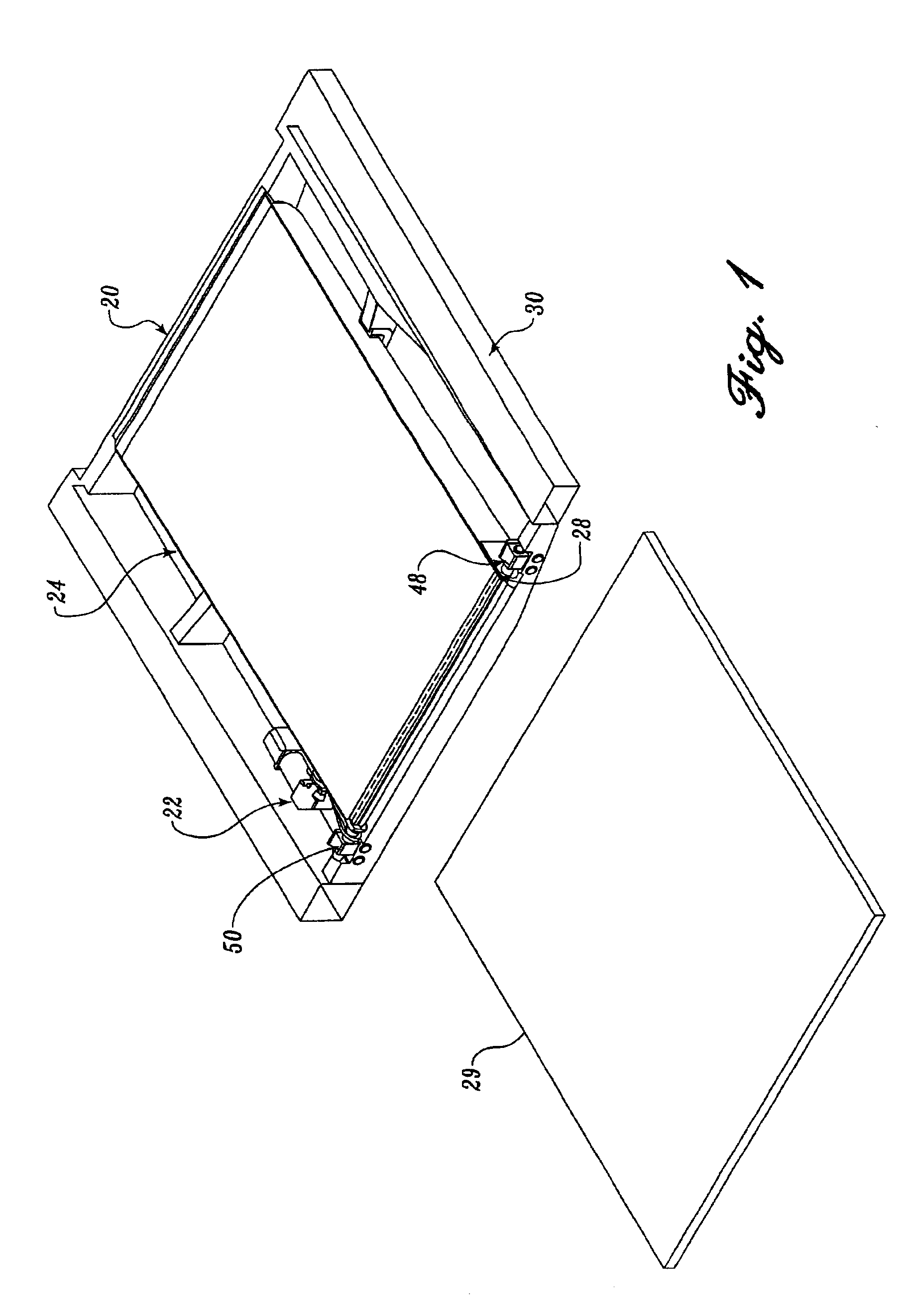
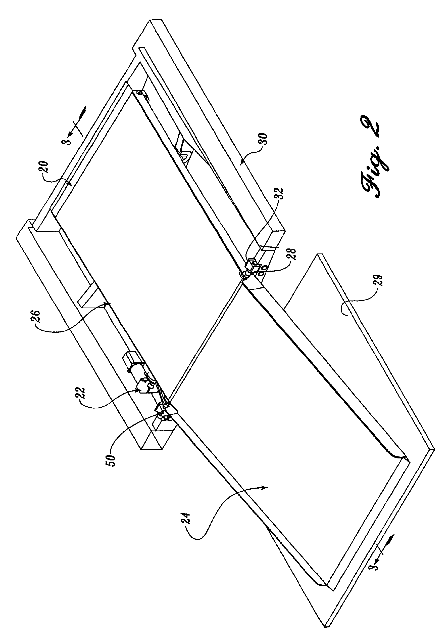
Referring now to FIGS. 47-68, a third alternate embodiment of the current invention will now be described in greater detail. Like the second alternate embodiment, the third alternate embodiment has two bearing points 3092a and 3092b. The fold-out ramp 3020, formed in accordance with the present invention, is similar in materials and operation to the alternate embodiments described above with the following exceptions. First, elements of the counterbalance linkage assembly 3022 have been repositioned or redesigned. Second, a new drive assembly 3024 (FIG. 52) has been provided. The moving floor 26 and 1026 of the previous embodiments has been replaced with a rising floor 3026. A clutch assembly 3028 has been added. A unitized frame 3999 has been added. Finally, a stow latch assembly 3030 has been added. For conciseness, only the foregoing exceptions will be described in greater detail.

Referring to FIGS. 47-50, the counterbalance linkage assembly 3022 will now be described in greater de...

first embodiment

The torsion arm 3036 has been moved with the repositioned torsion bar 3034. The torsion arm 3036 is similar to materials and operation to the torsion arm 1122 (FIGS. 22-26) of the first embodiment and the torsion arm 2122 (FIGS. 42-46) of the second alternate embodiment. As best seen in FIG. 48, the linkage and operation of the torsion arm 3036 and the actuating arm 3038 have not changed in this third alternate embodiment. The torsion arm 3036 extends between the torsion bar 3034 and the actuating arm 3038. One end of the torsion arm 3036 is pinned to a corresponding end of the actuating arm 3038 by a well-known pin 3039. The other end of the torsion arm 3036 is keyed to an end of the torsion bar 3034.

As best seen in FIG. 49, the free end of the actuating arm 3038 has first and second saddles 3040a and 3040b. First and second bearings 3042a and 3042b are positioned on the end of first stub shaft 3046a and engage saddles 3040a and 3040b in the same general way as described in the pre...


PUM


Abstract

A ramp assembly (20) having a frame attachable to a vehicle having a floor is disclosed. The ramp assembly further includes a platform coupled to a portion of the frame, a ramp having a weight, and a reciprocating mechanism disposed between the ramp and the platform coupled to a portion of the frame. The ramp assembly also includes a reciprocating mechanism disposed between the ramp and the platform for reciprocating the ramp between a deployed position and a stowed position in response to a load. The reciprocating mechanism counterbalancing the weight of the ramp during actuation of the ramp between the deployed and stowed positions to reduce the load required to reciprocate the ramp between the deployed and stowed positions.

Description

FIELD OF THE INVENTIONThe present invention relates generally to wheelchair lifts and, more particularly, to a fold-out ramp for a vehicle.BACKGROUND OF THE INVENTIONThe Americans with Disabilities Act (ADA) requires the removal of physical obstacles to those who are physically challenged. The stated objective of this legislation has increased public awareness and concern over the requirements of the physically challenged. Consequentially, there has been more emphasis in providing systems that assist such a person to access a motor vehicle, such as a bus or minivan.A common manner of providing the physically challenged with access to motor vehicles is a ramp. Various ramp operating systems for motor vehicles are known in the art. Some slide out from underneath the floor of the vehicle and tilt down. Others are stowed in a vertical position and are pivoted about a hinge, while still others are supported by booms and cable assemblies. The present invention is generally directed to a “...

Claims


Application Information

Patent Timeline
IPC IPC(8): B60P1/00B60P1/43
CPCB60P1/431B60P1/433Y10S414/134
Inventor COHN, ALAN
Owner ELEVATOR U DIV OF HOGAN MFG
Why Eureka
Try Eureka