
Sliding contact guide for transmitting medium

a contact guide and transmission medium technology, applied in the direction of couplings, manufacturing tools, gearing, etc., can solve the problems of increasing the difficulty of inserting metallic, increasing the time consumption of assembly of the guide, etc., to achieve the effect of enhancing the sandwiching of the reinforcing plate by the ribs, reducing the life of the guide, and improving the strength of the guid

Inactive Publication Date: 2005-01-18
TSUBAKIMOTO CHAIN CO
View PDF8 Cites 13 Cited by
  • Summary
  • Abstract
  • Description
  • Claims
  • Application Information

AI Technical Summary

Benefits of technology

The materials of the synthetic resin guide body are not especially limited. However, nylon 6, nylon 66, nylon 46, all aromatic nylons and the like, known as engineering plastics, have excellent wear and lubricating properties, and are preferably used. The transmission medium can slide easily on the surface of the shoe when the guide is composed of these materials. When bending rigidity, toughness and strength are required, fiber-reinforced plastics are preferred.
The guide in accordance with the invention allows a chain, a belt or other power transmission medium to slide in the longitudinal direction of the guide, while applying appropriate tension, suppressing widthwise vibration, and preventing widthwise movement of the traveling transmission medium such that it runs partly off the guide, or disengages the guide entirely.
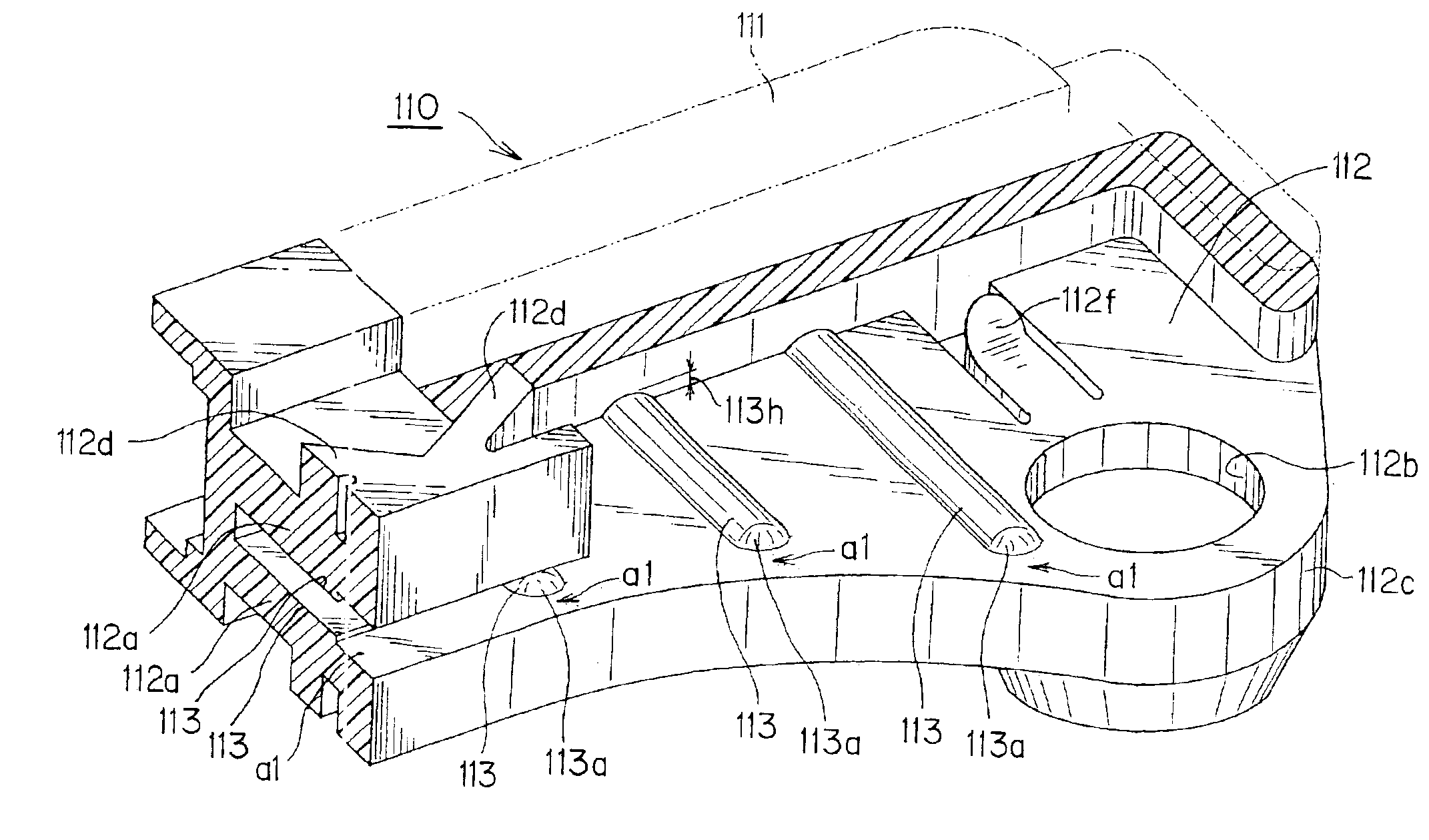
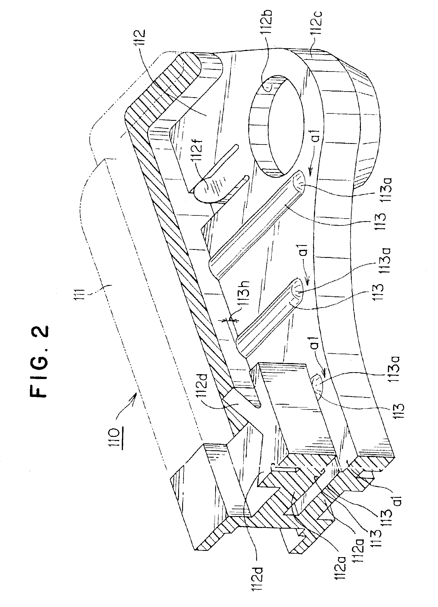
The ribs, which are raised ribs formed on the slot walls, are oriented in the direction of insertion of the reinforcing plate. Accordingly, the reinforcing plate can be inserted smoothly between the slot walls during assembly, since it moves in the direction of the lengths of the ribs while making linear contact with the ribs. When the reinforcing plate is fully inserted between the slot walls, the ribs sandwich the reinforcing plate, pressing it from both sides. Accordingly, the reinforcing plate is positively held between the slot walls and does not become dislodged from the guide body.
Furthermore, since the ribs formed are disposed in the direction of insertion of the reinforcing plate, that is, in a direction transverse to the shoe, from the back side of the shoe toward the medium-engaging surface thereof, the load exerted on the shoe by the transmission medium is sustained in part by the ribs, and thus the ribs themselves contribute to the bending rigidity, toughness, and strength of the guide. In addition, hollow spaces, having widths corresponding to the heights of the ribs, are produced between the walls of the guide body and the reinforcing plate. These spaces contribute to the release of heat generated by sliding friction in the operation of the guide.
When the mounting hole in the guide body and the hole in the reinforcing plate are aligned with each other and receive a fastener the sandwiching of the reinforcing plate by the ribs is further enhanced. Accordingly, contact vibration between the guide body and the reinforcing plate, which is produced during operation of the guide, is suppressed substantially completely.

Problems solved by technology

The wobbling movement of the reinforcing plate and guide body leads to a significant reduction in the life of the guide.
If the slot gap S is made small in order to avoid the above-described problems, it becomes more difficult to insert the metallic reinforcing plate 520 into the guide body 510, and assembly of the guide becomes more difficult and time-consuming, and in some cases may be impossible.
The result is a significant reduction in productivity.
However, to mold these parts in the same size is difficult.
Thus, excessive accuracy in molding, and very close dimensional tolerances were required.

Method used


Image

  • Sliding contact guide for transmitting medium
  • Sliding contact guide for transmitting medium
  • Sliding contact guide for transmitting medium

Examples


Embodiment Construction

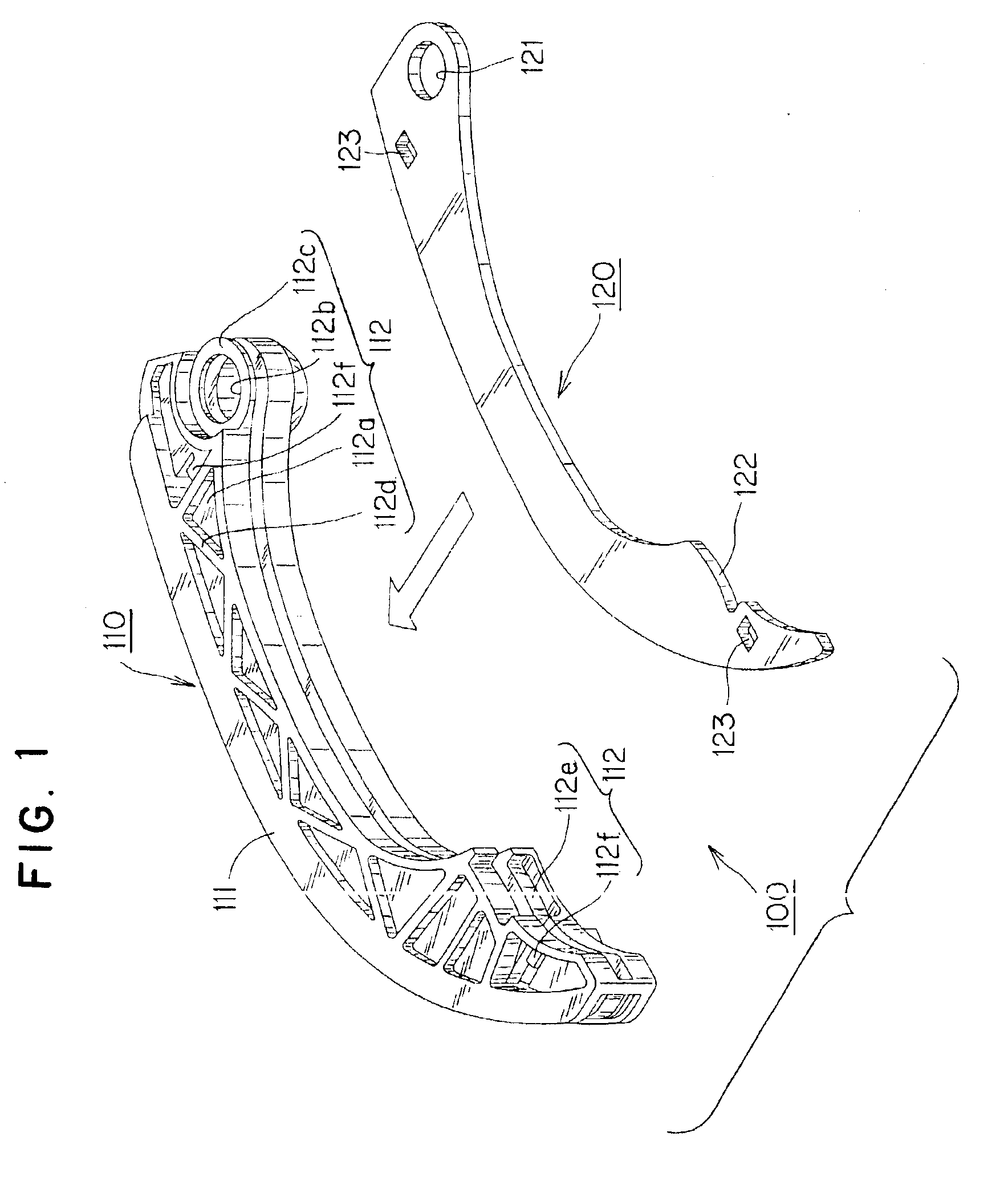
The sliding contact guide 100 shown in FIG. 1 is a sliding contact guide designed to serve as a tensioner lever. This guide is pivotally attached to an engine about a mounting shaft of the engine to maintain appropriate tension in a chain as the chain slides on the guide. The guide 100 is a two piece structure comprising an integrally molded, synthetic resin guide body 110 and a metallic reinforcing plate 120 punched from a steel sheet. The guide is produced by incorporating the reinforcing plate 120 into the guide body 110 by inserting the plate in the direction of the arrow as shown in FIG. 1.

This guide body 110 comprises a shoe 111 having a sliding surface on which a traveling chain slides, and a plate-receiving portion 112 on the back side of the shoe 111, composed of a pair of opposed walls 112a, which extend along the longitudinal direction of the guide. The plate receiving portion 112 includes a boss 112c having a mounting hole 112b for mounting the guide on a pivoting pin, b...


PUM


Abstract

A sliding contact guide for a chain, or other flexible transmission medium comprises a synthetic resin guide body having a shoe on which the transmission medium slides, and a slotted, plate-receiving portion on the back side of the shoe for receiving a reinforcing plate. The plate-receiving portion is composed of a pair of opposed, longitudinally extending, slot-defining walls. Raised ribs, for sandwiching the reinforcing plate, are disposed on opposed inner surfaces of the walls, and are oriented in the direction of insertion of the reinforcing plate into the slot. The guide suppresses shock noises due to wobbling of the guide during operation, and molding and assembly of the guide are enhanced.

Description

FIELD OF THE INVENTIONThis invention relates to a sliding contact guide for a power transmission utilizing an endless, circulating, flexible power transmission medium. It relates, for example, to a guide in a chain drive transmission, in which a chain transmits power from a driving sprocket to a driven sprocket, or to a guide in a belt drive transmission, in which a belt transmits power from a driving pulley to a driven pulley.BACKGROUND OF THE INVENTIONIn general, a chain or belt transmission device for valve timing in an internal combustion engine, or for transmitting rotational power in another drive mechanism, includes a chain or belt, which transmits power from a driving sprocket or pulley to one or more driven sprockets or pulleys. The transmission typically includes a pivotally mounted, movable, sliding contact guide, which cooperates with a tensioner, and a fixed sliding contact guide. The movable guide and the fixed guide are attached to a frame of the engine or other drive...

Claims


Application Information

Patent Timeline
Patent Type & Authority Patents(United States)
IPC IPC(8): F16H7/18F16H7/00F16H7/08
CPCF16H7/18Y10T403/1616F16H2007/0872
Inventor KONNO, MASAHIKO
Owner TSUBAKIMOTO CHAIN CO
Learn More