
Multi-function control key structure

a multi-functional, control key technology, applied in the direction of emergency actuators, electrical devices, electric switches, etc., can solve the problems of increasing manufacturing costs, reducing the service life of the key, and unable to meet the requirements of the 4-in-one multi-function key assembly, so as to prevent an accidental triggering action of the shank

Inactive Publication Date: 2005-01-18
TATUNG COMPANY
View PDF5 Cites 59 Cited by
  • Summary
  • Abstract
  • Description
  • Claims
  • Application Information

AI Technical Summary

Benefits of technology

It is the main object of the present invention to provide a multi-function control key structure, which is formed of only two parts that are easy and inexpensive to manufacture and, which prevents erroneous triggering during operation.
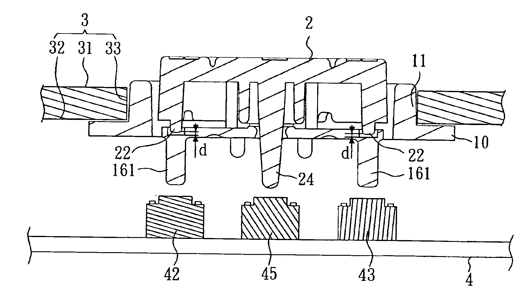
When pressing the border area of the key cap to force one driving rod against the respective triggering rod of the key body, the respective triggering rod trigger the respective key switch. At this time, the key cap is tilted to bias the shank, preventing an accidental triggering action of the shank. When pressing the center area of the key cap to force the shank to trigger the respective key switch, the action does not cause the triggering rods to make an accidental triggering action because the driving rods are kept away from the triggering rods at a distance.

Problems solved by technology

If an electronic device needs more than four control functions, a 4-in-1 multi-function key assembly cannot meet the requirement.
A 5-in-2 multi-function key assembly settles the insufficient function control problem of a 4-in-1 multi-function key assembly, however the additional center key unit greatly complicates the manufacturing process and increases the manufacturing cost.
However, this design of multi-function key assembly uses a big number of parts.
Further, the button of this design of multi-function key assembly may not return to its former position after having been pressed,

Method used


Image

  • Multi-function control key structure
  • Multi-function control key structure
  • Multi-function control key structure

Examples


Embodiment Construction

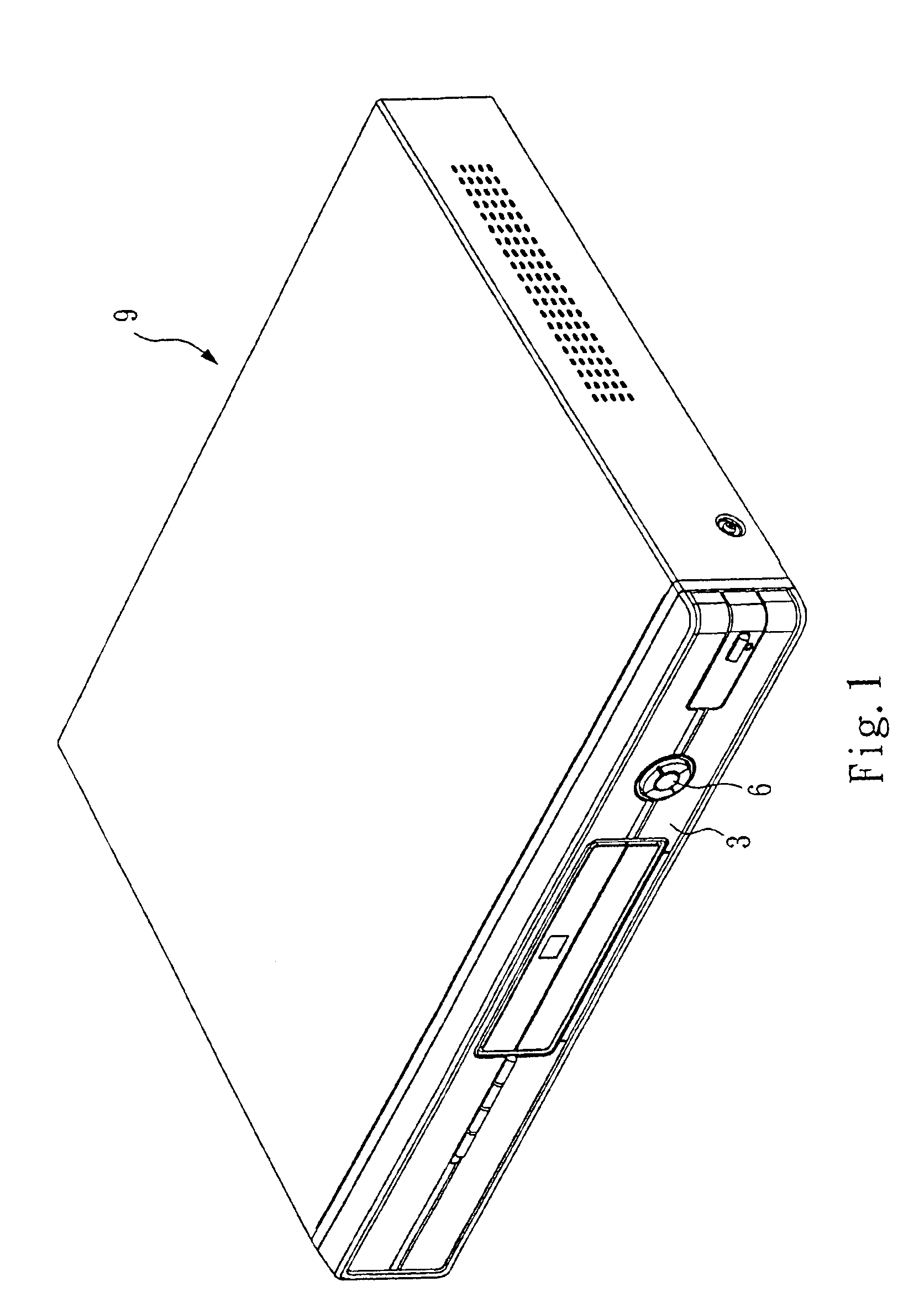
In FIG. 1, a computer 9 is shown having a front face panel 3 and a multi-function control key structure 6 installed in the front face panel 3.

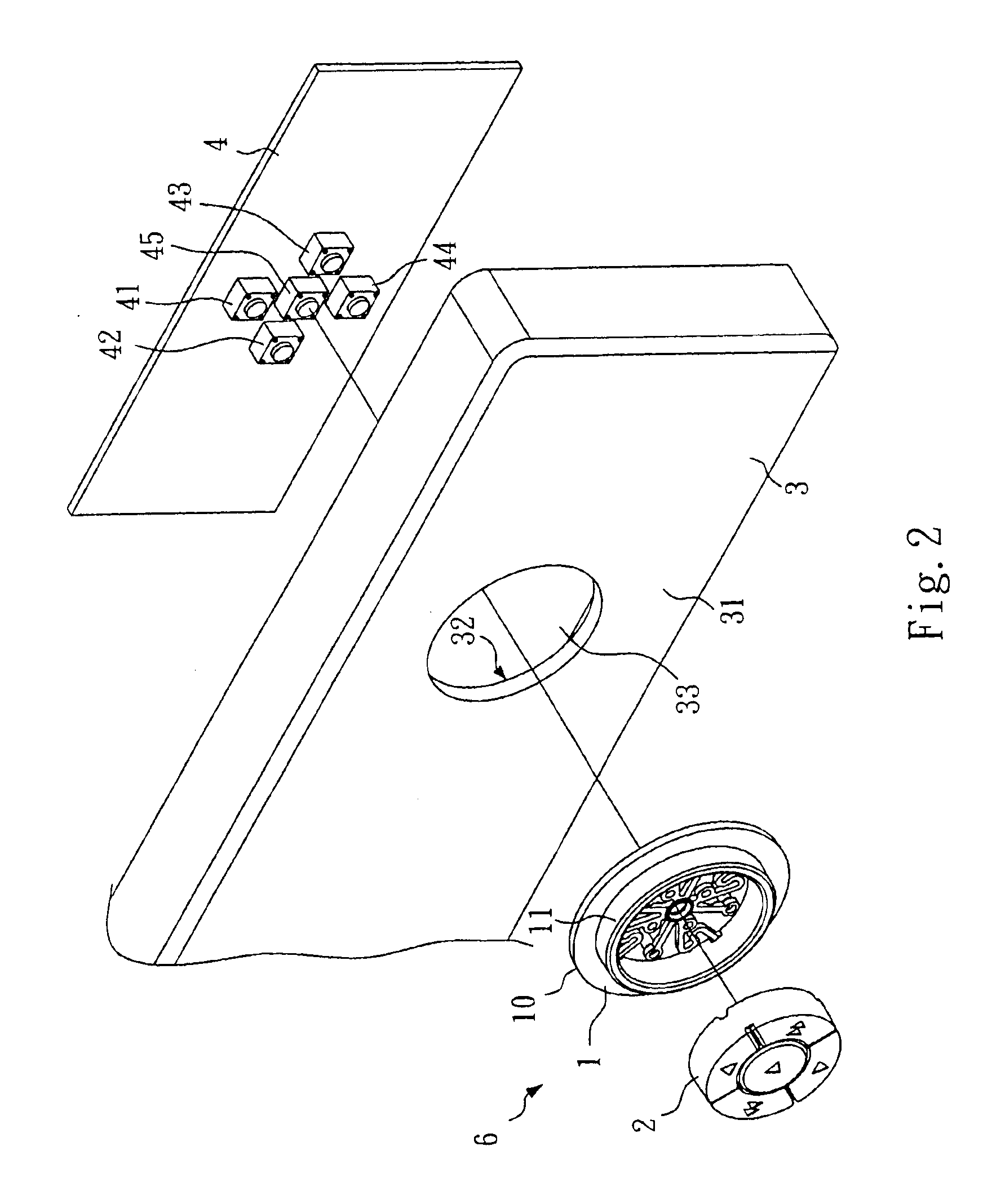
Referring to FIG. 2 and FIG 1, the front face panel 3 has an outer surface 31, an inner surface 32, and a through hole 33 extended through the outer surface 31 and the inner surface 32. The multi-function control key structure 6 comprises a springy key body 1 and a key cap 2. The key body 1 and the key cap 2 are installed in the front face panel 3.

Referring to FIGS. 3 and 4 and FIGS. 1 and 2 again, the key body 1 comprises a flat annular base 10 and an annular flange 11 protruded from one side of the flat annular base 10 around the inner diameter of the flat annular base 10. The annular flange 11 is inserted into the through hole 33 of the front face panel 3. The flat annular base 10 is bonded to the inner surface 32 of the front face panel 3 by heat sealing.

Further, the annular flange 11 of the key body 1 defines a center through hole 13. The...


PUM


Abstract

A multi-function control key structure formed of a key cap and a springy key body is disclosed for different triggering controls by means of a center shank of the key cap and a plurality of triggering rods of the key body around the center shank. The key cap has driving rods spaced above the triggering rods and adapted to drive the triggering rods to make a triggering action respectively. The center shank is tilted so as not to make a triggering action accidentally when the key cap is biased to force one triggering rod of the key body to make a triggering action. The driving rods do not touch the triggering rods when pressed the center area of the key cap to force the center shank to make a triggering action.

Description

BACKGROUND OF THE INVENTION1. Field of the InventionThe present invention relates to a multi-function control key structure for an electronic device, for example, a computer, video cassette player / recorder, remote controller, etc.2. Description of Related ArtAn electronic consumer product may be provided with a so-called multi-function key assembly, which has a button exposed to the outside for multiple function controls, for example, up, down, left, right controls.Regular multi-function key assemblies include two types, namely, the so-called 4-in-1 and the so-called 5-in-2. A 4-in-1 multi-function key assembly provides up, down, left, and right control functions. If an electronic device needs more than four control functions, a 4-in-1 multi-function key assembly cannot meet the requirement. Further, a 5-in-2 multi-function key assembly comprises an outer key unit and a center key unit. The outer key unit provides up, down, left, right controls. The center key is for another functio...

Claims


Application Information

Patent Timeline
IPC IPC(8): H01H25/04G06F3/02H01H25/06
CPCH01H25/041H01H2221/044
Inventor HSU, MING-CHUNTSOU, HSIEN-PINLUO, BO-SHIUN
Owner TATUNG COMPANY
Learn More