LCD drive apparatus
a technology of lcd drive and driver device, which is applied in the direction of instruments, computing, electric digital data processing, etc., can solve the problems of increased current consumption and achieve the effects of reducing disturbance of displayed image, increasing current consumption, and keeping current consumption extremely low
- Summary
- Abstract
- Description
- Claims
- Application Information
AI Technical Summary
Benefits of technology
Problems solved by technology
Method used
Image
Examples
first embodiment
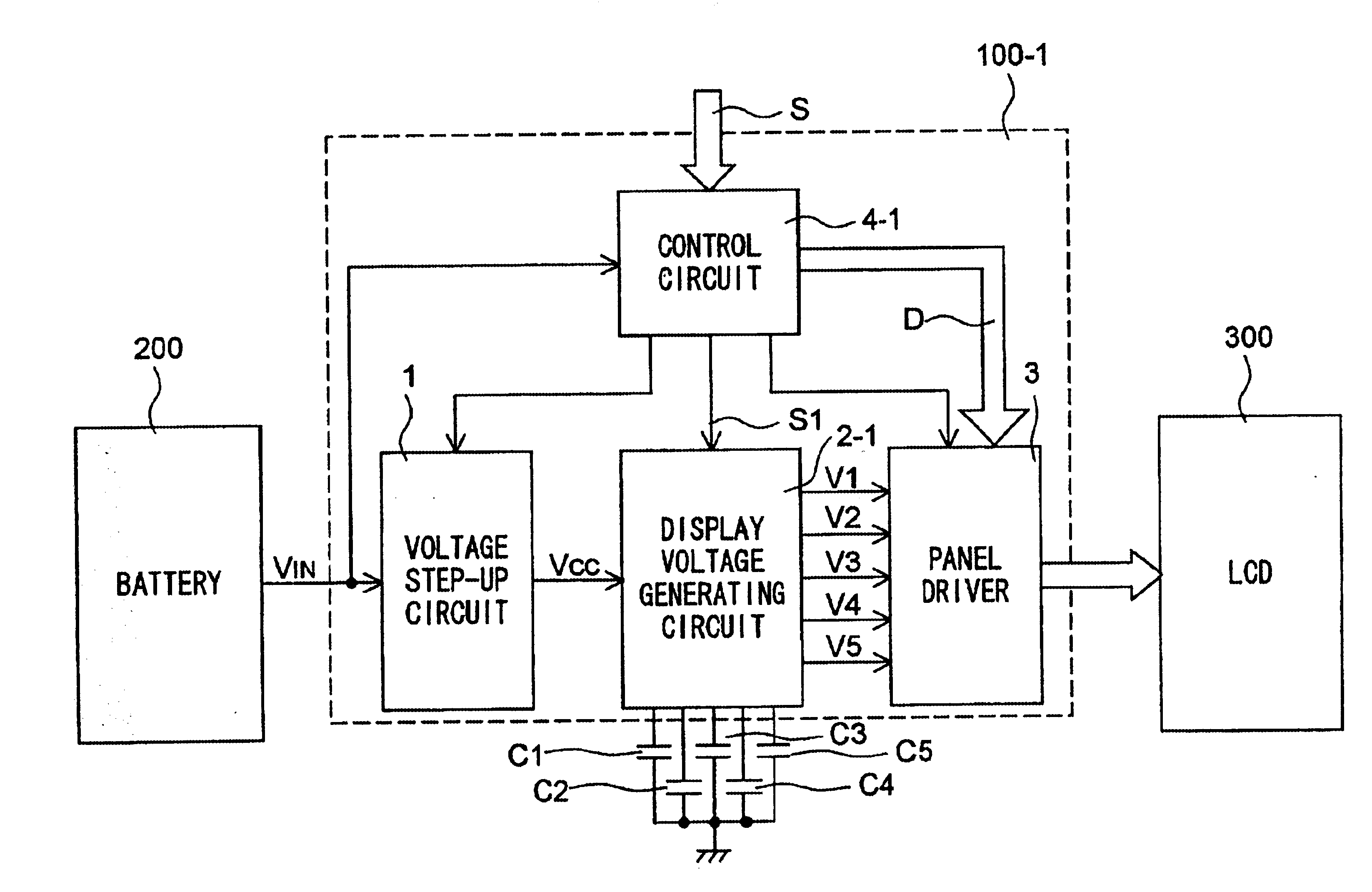
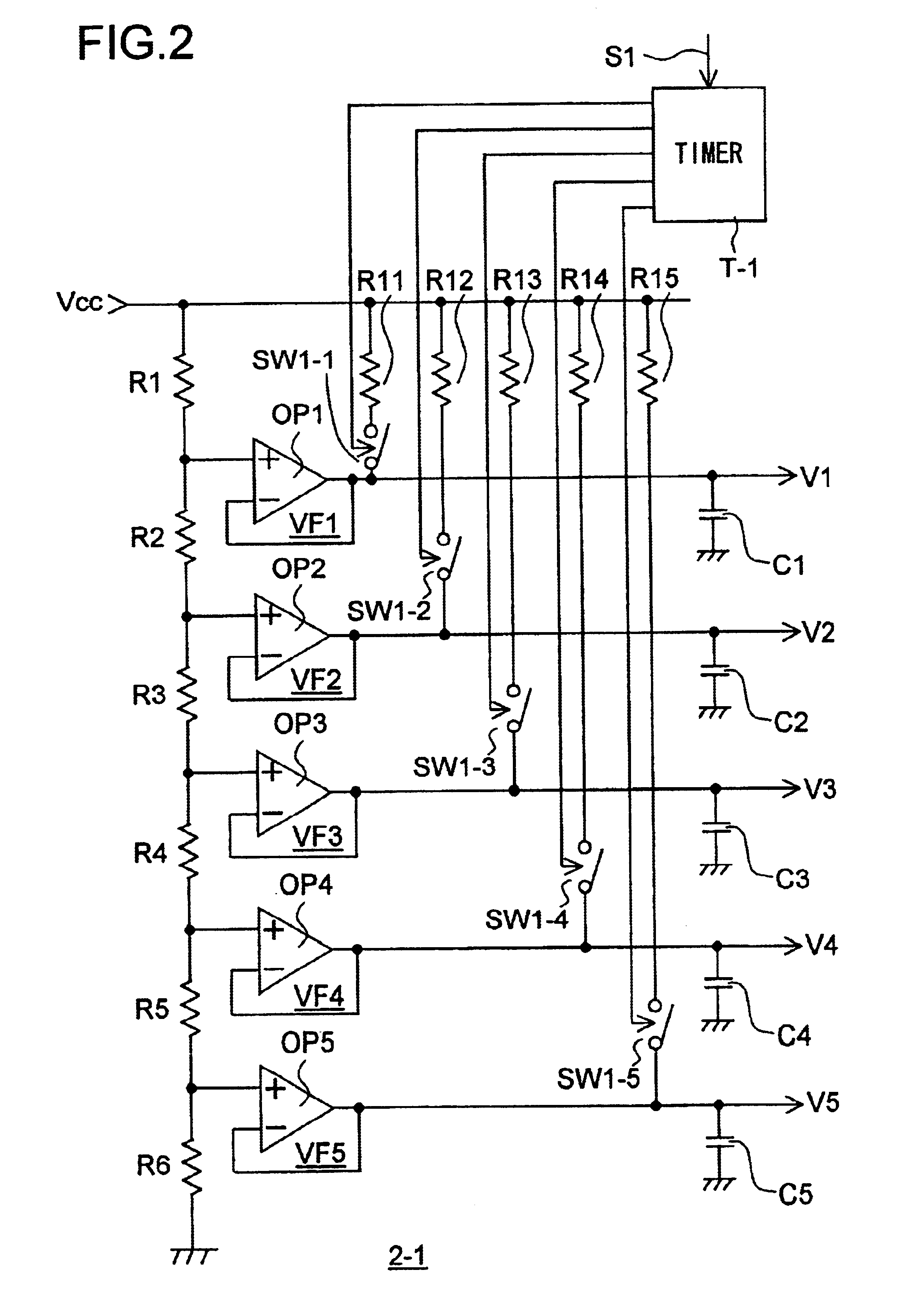
Moreover, in the first embodiment, each capacitor is charged with the supply voltage VCC for the period that is assumed to be required for the corresponding display voltage to reach the prescribed level after the display voltage generating circuit 2-1 starts operating. This makes it possible to minimize the required period without increasing ineffective electric power consumption due to current that flows through the capacitors after the display voltages V1, V2, V3, V4, and V5 have reached the prescribed levels.
FIG. 3(b) shows how the individual output voltages rise to the prescribed voltages V1, V2, V3, V4, and V5 and behave thereafter when the resistors R11 to R15 are given the same resistance. In this case, each output voltage takes a different length of time to reach the prescribed level. Accordingly, the switch corresponding to each output voltage is turned off with different timing.
If all of the first group of switches are turned off simultaneously after all of the display vol...
second embodiment
Moreover, in the second embodiment, each capacitor is charged with the supply voltage VCC for the period that is assumed to be required for the corresponding display voltage to reach the prescribed level after the display voltage generating circuit 2-2 starts operating. This makes it possible to minimize the required period without ineffective electric power consumption before display is started on the LCD 300.
When display is stopped, all of the second group of switches are turned off when the supply of electric power to the display voltage generating circuit 2-2 is shut off. At the start of operation, the second-group switches are turned on one by one as the corresponding first-group switches are turned off one after another. Alternatively, all of the second group of switches may be turned on simultaneously when all of the first group of switches have been turned off. This helps simplify the configuration of the timer T-2. Since the display voltages are not supplied to the panel dr...
PUM
| Property | Measurement | Unit |
|---|---|---|
| voltage | aaaaa | aaaaa |
| bias voltage | aaaaa | aaaaa |
| supply voltage | aaaaa | aaaaa |
Abstract
Description
Claims
Application Information
 - R&D
- Intellectual Property
- Life Sciences
- Materials
- Tech Scout
- Unparalleled Data Quality
- Higher Quality Content
- 60% Fewer Hallucinations
Browse by: Latest US Patents, China's latest patents, Technical Efficacy Thesaurus, Application Domain, Technology Topic, Popular Technical Reports.
© 2025 PatSnap. All rights reserved.Legal|Privacy policy|Modern Slavery Act Transparency Statement|Sitemap|About US| Contact US: help@patsnap.com


