Optical high-density distribution frame and method for making jumper connections in such a distribution frame

a high-density, optical technology, applied in the field of optical distribution frames, can solve problems such as interference in telecommunications, optical fiber displacement, and insatiable results

Inactive Publication Date: 2005-01-18
NEXANS
View PDF10 Cites 115 Cited by
  • Summary
  • Abstract
  • Description
  • Claims
  • Application Information

AI Technical Summary

Problems solved by technology

This kind of solution was initially developed for jumpers consisting of electrical wires, and is not satisfactory if the distribution frame to be produced is a high-density distribution frame with a very high capacity, involving the fitting of a very large number of optical jumpers, for example ten thousand or more, which may be fragile and which must therefore be protected from damage, in particular during reorganization.
Such a distribution frame poses the following essential technical problem: it is very bulky.
Another technical problem relates to the fact that the connection areas can move and consequently the optical fibers are displaced during connections.
This may cause interference in the telecommunications.

Method used


Image

  • Optical high-density distribution frame and method for making jumper connections in such a distribution frame
  • Optical high-density distribution frame and method for making jumper connections in such a distribution frame
  • Optical high-density distribution frame and method for making jumper connections in such a distribution frame

Examples


first embodiment

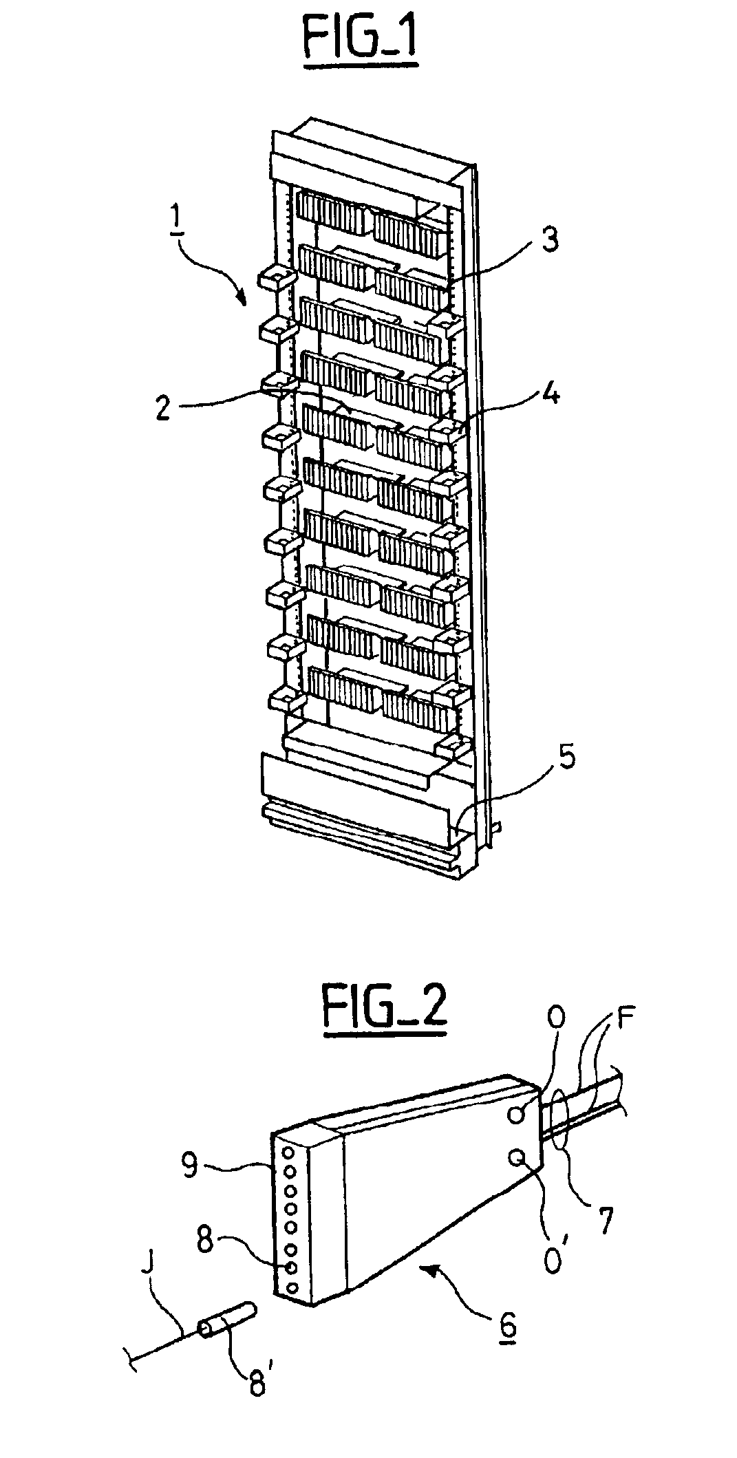
In the proposed embodiment, means are provided at the end of a support arm which includes a central housing 21 that cooperates with complementary means provided on a device by means of which a plug is located in front of the connection member compartment 8 into which it must be inserted. In the embodiment described, the means provided at the end of a support arm are hollow shapes adapted to receive complementary solid shapes, these shapes being chosen to achieve the positioning accuracy necessary for inserting a plug in the connection position into a conduit of a connection member whose position in the distribution frame has been predetermined. In a first embodiment, the means provided at the end of a support arm take the form of cylindrical cavities 22A at the first end of each arm and each extended laterally by a slot 22B with a particular orientation. The socket 6 is immobilized in the arm in a particular position, this position being confirmed by a polarizer 22C provided inside ...

second embodiment

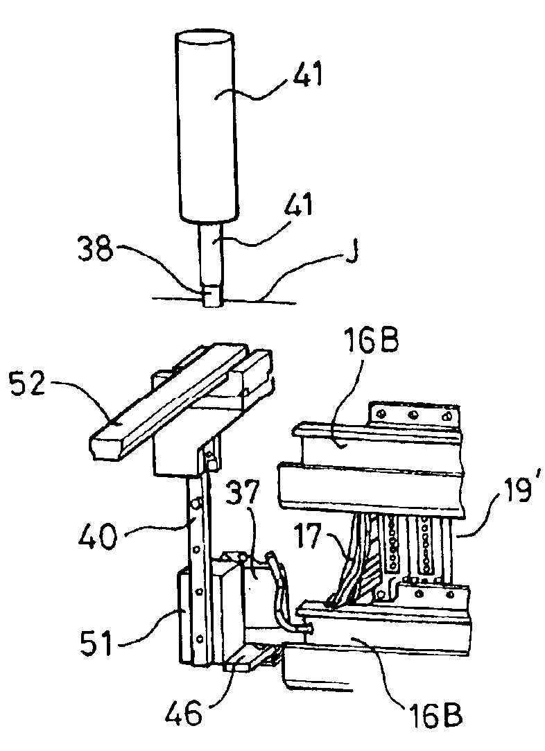
In a second embodiment, the plug positioning device can be accurately positioned relative to one of the cylindrical cavities 22A disposed around the opening of the housing 21 of a support arm 19. To this end, the positioning device is displaced mechanically to a predetermined position relative to the distribution frame, or to be more precise relative to a connection member 8 of a socket 6 accurately positioned in one of the racks of the distribution frame. The penetration of the centering rod of the plug positioning device into a particular cylindrical cavity 22A can then serve, incidentally, to pre-position the tool of the device used to insert a plug into the conduit of a particular connection member 8 of a particular socket 6. The tool is then designed so that the plug has some facility for accommodation and relative freedom of lateral movement on insertion. This facility is provided by one or more springs where the tool is fixed to the device that carries it, for example.

In the ...


PUM


Abstract

The distribution frame and the method relate to a telecommunication installation in which optical fiber links are connected to connection members formed by sockets distributed on the front face of at least one distribution rack and in which jumpers provide the links between the connection members to which the links are individually connected. A robotized set of specialized tools is provided:to mount a plug on one end of a jumper reserve stored in coiled form;to position the plug in a connection member of a socket;to fit the jumper uncoiled from this member as far as another member;to adjust the length and to cut a section of uncoiled jumper; andto mount a plug on the end of the section and to position this plug in the other member.

Description

BACKGROUND OF THE INVENTION1. Field of the InventionThe invention relates to an optical distribution frame, more particularly intended for allowing interconnections which are made selectively between optical fiber links in a telecommunication installation comprising a large number of these fiber links.It also relates to a method intended for making jumper connections between fibers by means of which these interconnections are made, in an optical distribution frame having a high density of interconnection points, as envisioned above.2. Description of the Prior ArtU.S. Pat. No. 5,497,444 describes one example of an optical distribution frame for use in telecommunication installations. It is shown in FIG. 1 and has a rectangular framework 1 which carries a series of horizontal supports 2 on which are placed modules 3 which are arranged on the supports so that they constitute two parallel vertical subassemblies. Each module is designed to accommodate a plurality of connectors, each conn...

Claims


Application Information

Patent Timeline
Patent Type & Authority Patents(United States)
IPC IPC(8): G02B6/38G02B6/44G02B6/00
CPCG02B6/4455G02B6/3885G02B6/3874
Inventor THIBAULT, JEAN-PIERREVINCENT, ALAINLEPEUVE, ALAINJOLY, BERTRANDLECOMTE, DIDIER
Owner NEXANS
Why Eureka
Try Eureka