
Video apparatus and re-encoder therefor

a video and re-encoding technology, applied in the field of video equipment, can solve the problems of not having a video apparatus that can be used as a stand-alone re-encoding apparatus, no video apparatus that can be used for enhancing the capability of re-encoding, and no internal provision for embedding new in the video apparatus

Inactive Publication Date: 2005-01-18
NEC CORP
View PDF9 Cites 22 Cited by
  • Summary
  • Abstract
  • Description
  • Claims
  • Application Information

AI Technical Summary

Benefits of technology

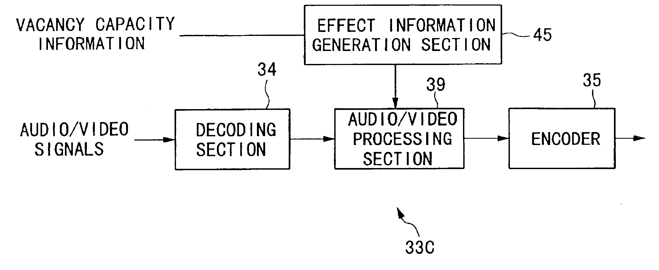
It is an object of the present invention to provide a video apparatus capable of controlling the file size of audio / video data recorded on a recording medium.
The ninth effect of the present invention is that the present video apparatus enables to readily enhance the re-encoding capability.

Problems solved by technology

Therefore, the video apparatus does not have any internal provision for embedding new reproduction managing information into the recording medium, immediately prior to starting to accumulate the audio / video signals distributed from network, broadcasting or other video apparatus.
Also, according to the conventional technology, if the vacancy capacity in the recording medium becomes insufficient, it is not possible to manipulate the audio / video signals themselves to facilitate further recording.
Furthermore, according to the conventional technology, there is no video apparatus that can be used as a stand-alone re-encoding apparatus, whose re-encoding capability can be enhanced by connecting to another re-encoder.
The conventional technology described above presents the following problems.
The first problem is that there is no method for controlling the file size of the audio / video signals recorded in the video apparatus.
The reason is that it is not possible to manipulate the audio / video signals without decoding first.
The second problem is that it is not possible to insert character / diagrams / voice / and image information to the audio / video signals to be recorded in the video apparatus.
The third problem is that it is not possible to embed reproduction managing information that is operative even after decoding the audio / video signals recorded in the video apparatus.
The fourth problem is that, if the vacancy capacity in the recording medium becomes depleted while recording the audio / video signals in the video apparatus, there is no provision for manipulating the audio / video signals themselves to facilitate further recording.
It follows that it is not possible to reduce the file size of the audio / video signals to be recorded.
It is also not possible to display special effects such as a warning sign in the reproduced audio / video signals by simply carrying out reproducing and decoding operations on the recorded audio / video signals.
The fifth problem is that it is not possible to accommodate in one file a number of audio / video signal streams generated by encoding audio / video data, even when it is known that the data are to be displayed on a common screen or to be played on a common speaker.
Or, even if the data can be integrated in one file, in reality, the file size is a sum of the file sizes of the various audio / video signal streams, and therefore, reduction in file size cannot be effected.
The sixth problem is that the conventional video apparatus is not able to re-encode audio / video input signals in real-time and to encode the same audio / video signals to generate thumbnail video images in real-time.
The seventh problem is that the conventional video apparatus is not able to re-encode audio / video input signals in real-time and to encode the audio / video signals to generate sample video images for searching purposes by extracting frames from the audio / video signals.
The eighth problem is that the conventional video apparatus is not able to re-encode audio / video input signals in real-time, and, to capture and output still images in real-time by encoding the same audio / video signals.
The ninth problem is that the conventional encoder is not readily amenable to enhancing its re-encoding capability.

Method used


Image

  • Video apparatus and re-encoder therefor
  • Video apparatus and re-encoder therefor
  • Video apparatus and re-encoder therefor

Examples


first embodiment

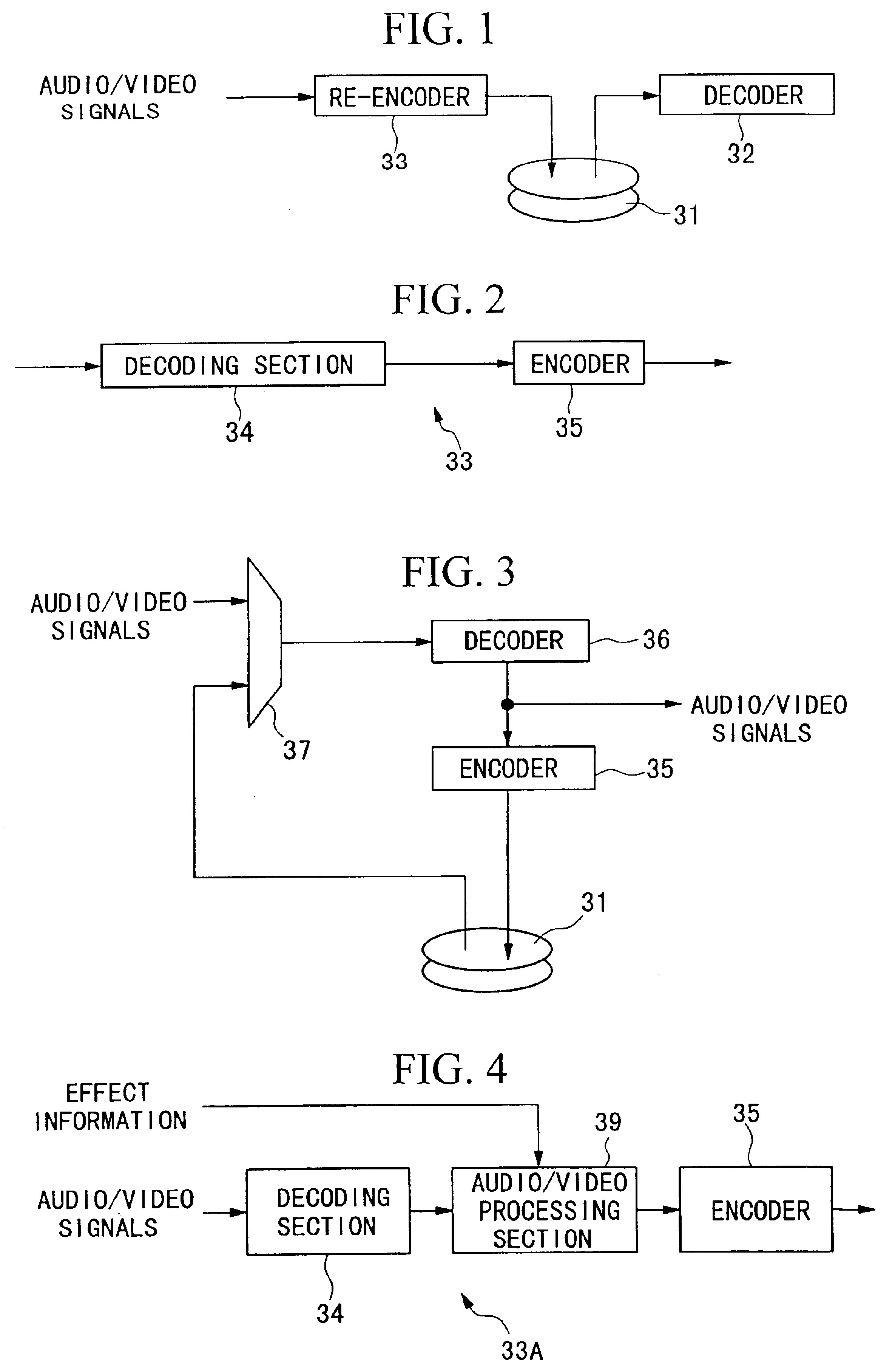
FIG. 1 is a block diagram of the video apparatus.

The video apparatus is comprised by a recorder 31 representing a recording medium, a decoder 32 and a re-encoder 33.

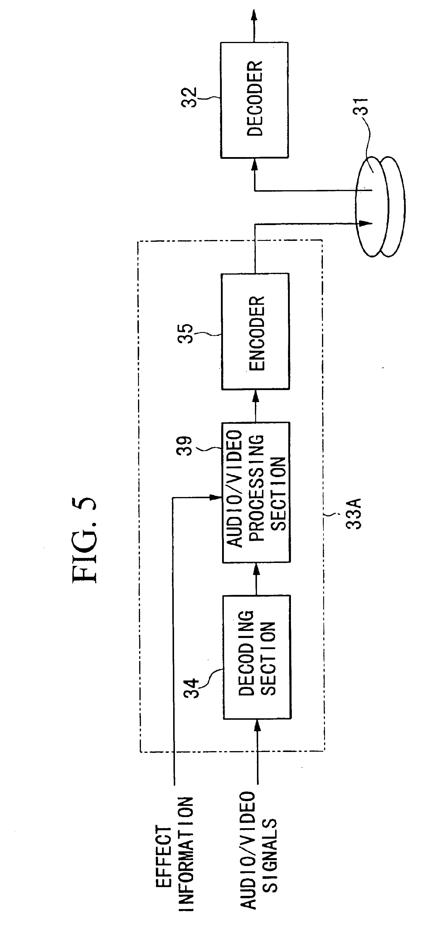
The operation of the video apparatus shown in FIG. 1 will be explained. First, audio / video signals input into the video apparatus or audio / video signals generated within the video apparatus are input into the re-encoder 33. The re-encoder 33 re-encodes the audio / video input signals, and outputs re-encoded audio / video signals. The re-encoded audio / video signals are accumulated in a recorder 31 as accumulated audio / video signals. The accumulated audio / video signals read from the recorder 31 are supplied as readout audio / video signals to a decoder 32. The decoder 32 decodes the readout audio / video signals, and externally outputs decoded audio / video signals as audio / video output signals.

FIG. 2 shows an example of the configuration of the re-encoder 33 used in the video apparatus. The re-encoder 33 is comprised by a decoding ...


PUM


Abstract

The present video apparatus is provided with a re-encoder having an audio / video processing section disposed between a decoder and an encoder so that the decoded audio / video signals can be re-encoded. Image resolution of the video information is altered by the audio / video processing section so as to control the bit-rate of the audio / video encoding process performed in the encoding section to suit the system performance. Such a configuration of the video apparatus enables to control the file size of the audio / video codes recorded in a recording medium of the recorder. It is also possible to use the audio / video processing section to insert characters, diagrams and image information in the video data, and to insert additional audio data in the original audio data.

Description

BACKGROUND OF THE INVENTION1. Field of the InventionThe present invention relates to a video apparatus for processing encoded audio and video signals, and relates in particular to a video apparatus having a device to enable re-encoding the audio and video signals.2. Description of the Related ArtAn example of the conventional video apparatus is shown in FIG. 21. As shown in FIG. 21, compression encoded audio / video signals are recorded in a video apparatus in the following manner. Video and image input signals are stored on a recording medium 31 in a recording device, and the signals recorded on the recording medium 31 are reproduced and decoded in the decoder 32, and the decoded signals are output externally.Also, FIG. 22 shows another example of the conventional video apparatus for processing compression encoded audio / video signals or applying special effects to the data. As shown in FIG. 22, processing or applying special effect to the data is carried out after decoding the reprod...

Claims


Application Information

Patent Timeline
IPC IPC(8): H04N7/26H04N7/52G06F21/10H04N5/92G11B20/00G11B20/10G11B27/00G11B27/02G11B27/031H03M7/30H04N19/00H04N19/115H04N19/117H04N19/126H04N19/132H04N19/136H04N19/15H04N19/152H04N19/172H04N19/176H04N19/186H04N19/196H04N19/40H04N19/423H04N19/426H04N19/46H04N19/463H04N19/467H04N19/48H04N19/503H04N19/587H04N19/70H04N21/236H04N21/2365H04N21/2368H04N21/433H04N21/434H04N21/4402H04N21/442H04N21/462
CPCH04N21/23614H04N21/2368H04N19/40H04N21/4348H04N19/115H04N21/4341H04N21/2365H04N21/4334H04N21/4402H04N21/4424H04N21/4621
Inventor FUNAYA, KOICHIOOTSUKA, OSAMU
Owner NEC CORP
Learn More