Toothed daylight blinds

a technology of blinds and guiding rods, applied in the direction of lighting and heating equipment, building components, constructions, etc., can solve the problems of neither overheating nor glare by the panes, and achieve the effect of excluding glare in the outer panes

Inactive Publication Date: 2005-01-25
KOSTER HELMUT
View PDF6 Cites 156 Cited by
  • Summary
  • Abstract
  • Description
  • Claims
  • Application Information

AI Technical Summary

Benefits of technology

[0013]The advantage of the invention is that by the concave shape of the prismatic toothed upper side of the blinds by one single reflection, retro-reflection is in principle retro-reflected at an angle αR<αS back to the exterior space. αS constitutes the position of a connecting line between the edge of a lower blind in the irradiation area and the edge of an upper blind in the deflection area on the interior space side. αR constitutes the angle of the retro-reflected, or back-reflected, respectively, radiation related to the irradiation level, or the glazing level, respectively. The irradiation level is configured by at least two blind edges each of an upper blind edge each and a lower blind edge each in the irradiation area as viewed from the outer space. The reflection cross section is configured by at least two blind edges each of an upper blind edge each and a lower blind edge each in the reflection area as viewed from the interior space. If αR<αS, then it is guaranteed that there is no direct glare by reflection in the outer panes. For flatter angles of incidence or other positions of the blinds, respectively, glare-free retroreflection is also guaranteed by two reflections. By the shape according to the invention of the tooth sides showing to the sun, the light reflected from the upper side of a blind to the underside of the upper blind falls at an angle γ<90°, which leads to a light guidance on the inner side of the outer pane from above so that a reflection of the retro-reflected radiation cannot generate any disturbing glare effect in the interior space (FIG. 4). The radiation retro-reflected at the panes is again received by the upper side of the lower blind and is retro-reflected again.
[0014]The present invention constitutes a construction guideline according to which stepped or toothed blinds can be constructed so that glare in the outer panes is extensively excluded. Examples will explain the idea of the invention and interesting embodiments.

Problems solved by technology

Neither the problem of overheating nor glare by the panes is acceptable.

Method used


Image

  • Toothed daylight blinds
  • Toothed daylight blinds
  • Toothed daylight blinds

Examples


Embodiment Construction

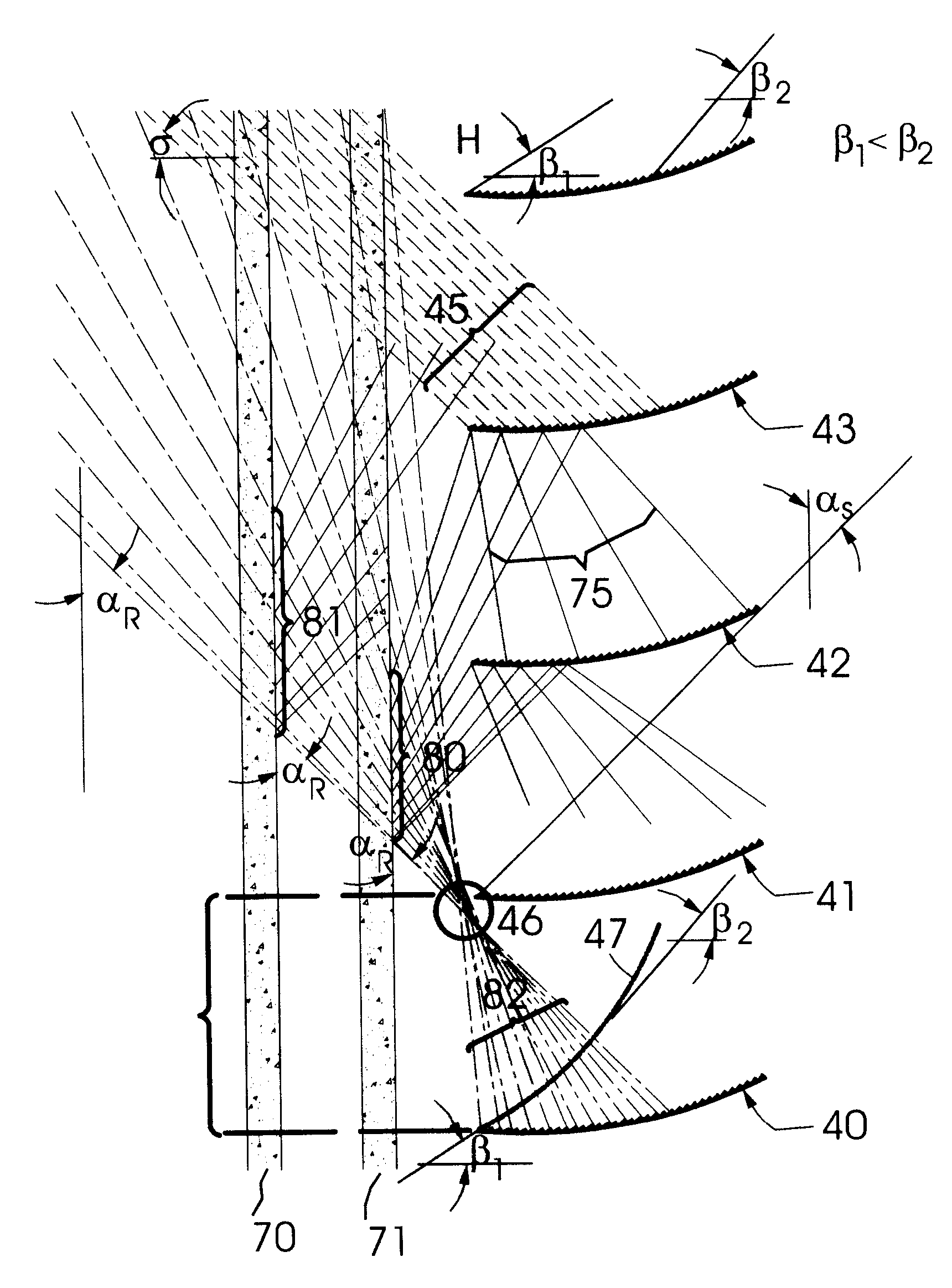
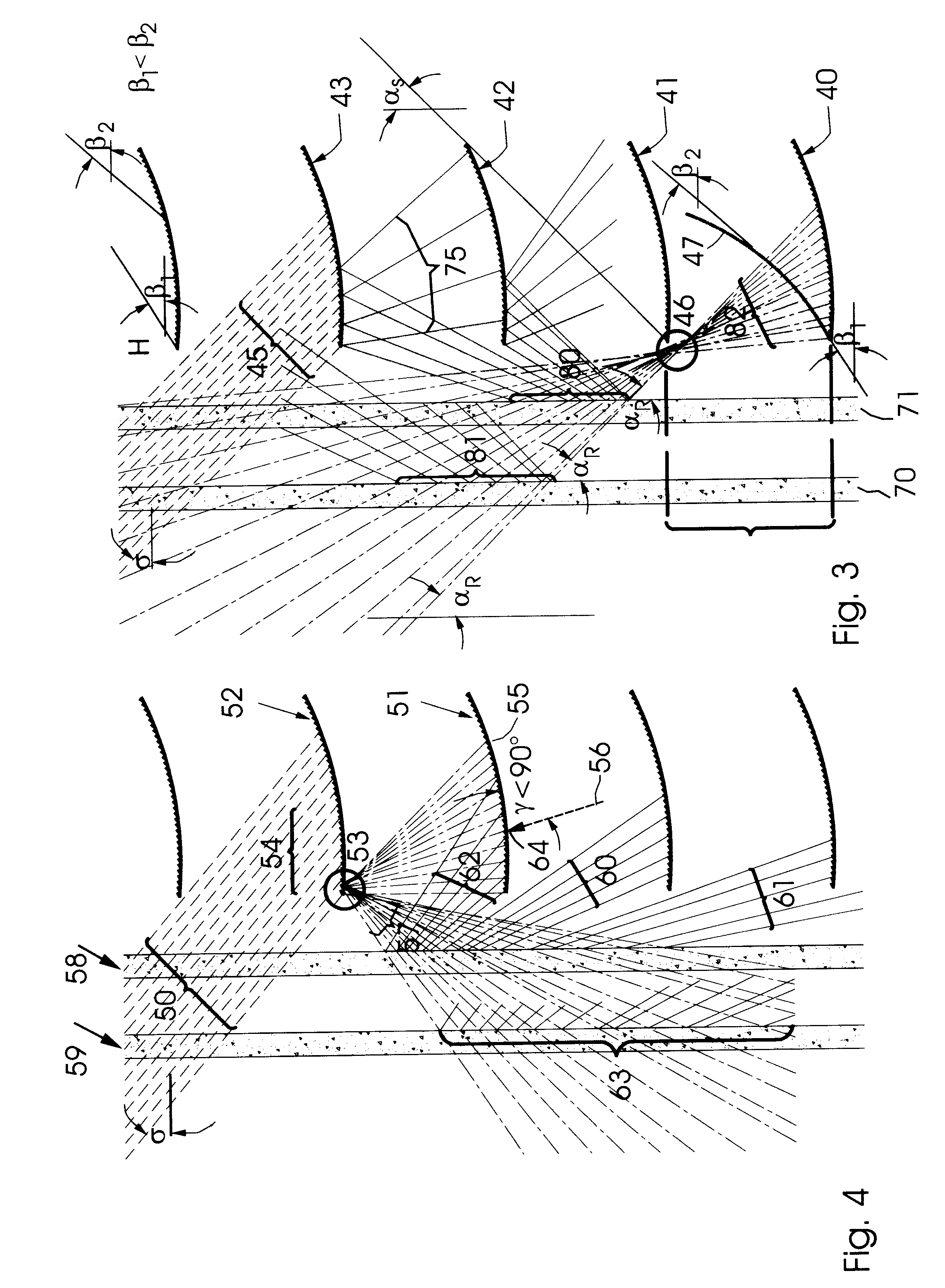
analysis of the ray paths for the innovative light guiding blinds in operable blind positions.

[0018]FIGS. 5, 6, and 7 show further exemplified embodiments of the blinds of the invention.

[0019]FIG. 8 shows an innovative production process of microstructuring by coating with sol gel.

[0020]FIG. 9 shows an enlargement of a microstructurated surface.

DETAILED DESCRIPTION OF THE INVENTION

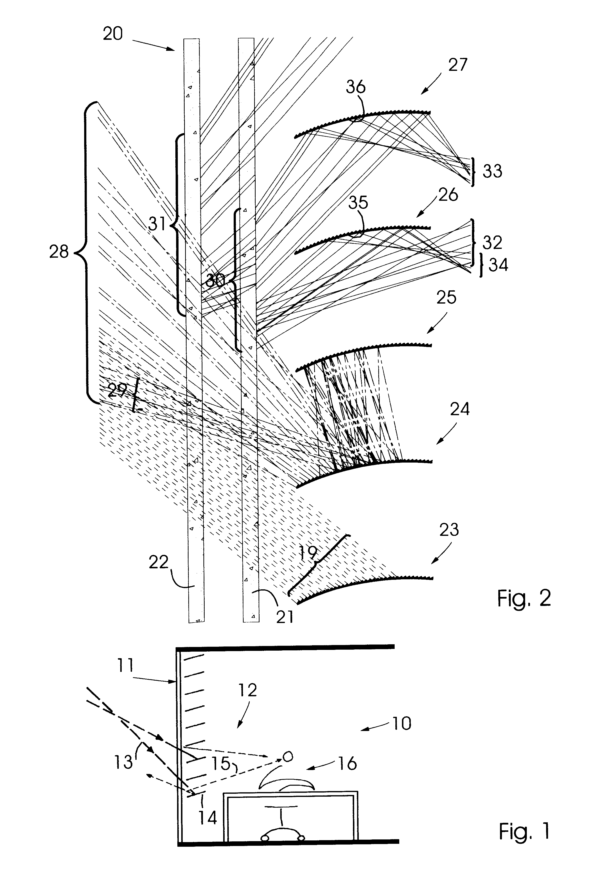
[0021]FIG. 1 shows, as known from the prior art, the cross section through an interior space 10 one side 11 of which is glazed. Behind the glazing, a daylight guiding venetian blind having reflective surfaces 12 is arranged. The problem is explained based on ray path 13. Inciding light radiation impinges on blind 14 and is retro-reflected by it into glass faced 11. In glass facade 11, a reflection is generated which, as shown by ray path 15, produces glare in the eye of observer 16. All prior-art retro-reflective blind structures having reflective upper sides, even prismatic retro-reflectors, show glare ef...


PUM


Abstract

The flight guiding blinds of this invention are characterized in that the tooth sides showing towards sun incidence have an angle of inclination β essentially smaller in the area of the irradiation portion and larger at a larger distance from the irradiation portion, and the angles of inclination β increase following a concave curve path increasingly ascending from the irradiation area towards the reflection area, and at the upper side of light guiding blinds retro-reflected reaction is concentrated and a concentration zone is formed near irradiation portion and the concentration zone is disposed either in front of blind in the irradiation portion and/or on the underside of upper blind behind the irradiation portion, and on the upper side of a light guiding blind light radiation may be reflected at the individual teeth at and angle αRS.

Description

BACKGROUND OF THE INVENTION[0002]1. Field of the Invention[0003]The present invention relates to light guiding blinds in accordance with the preamble of the main claim.[0004]2. Prior Art[0005]It has been known to provide blinds having toothed shape at the upper side thereof. In DE 195 43 811 A1 and in DE 42 39 003 C2, blinds are shown having a stepped, or toothed, respectively, upper side by which retro-reflection of the sun radiation impinging on the blinds can be effected.[0006]From DE 196 03 293 A1 or from AT 394 883 B, furthermore, blinds have been known which include, towards sun incidence, a first portion which retro-reflects incident sun radiation into the exterior space.[0007]A disadvantage of all these prior art devices preferably arranged in an interior space behind a glazing is to be seen in that sun radiation retro-reflected at the upper side of the blinds is guided, at least partly, at a very flat angle to the inner side of the roof or facade glazing. Particularly in ca...

Claims


Application Information

Patent Timeline
Patent Type & Authority Patents(United States)
IPC IPC(8): E06B9/386E06B9/38F21S11/00
CPCE06B9/386F21S11/00E06B2009/2417
Inventor KOSTER, HELMUT
Owner KOSTER HELMUT
Why Eureka
Try Eureka