Ink jet recording apparatus and cleaning control method for recording head incorporated therein

a recording apparatus and cleaning control technology, applied in the field ofink, can solve the problems of increasing the cost of the whole recording apparatus, and increasing the size of the recording apparatus, and achieve the effect of preventing the breakage of the ink storage section

Inactive Publication Date: 2005-01-25
SEIKO EPSON CORP
View PDF14 Cites 32 Cited by
  • Summary
  • Abstract
  • Description
  • Claims
  • Application Information

AI Technical Summary

Benefits of technology

Owing to the configuration, breakage of the ink storage section can be prevented, ink ...

Problems solved by technology

Since ink pressurized in a pressure generating chamber is jetted to recording paper as ink drops from a nozzle for printing, the recording head involves a problem of causing a print failure because of a rise in the ink viscosity and hardening of ink caused by vaporization of a solvent from nozzle orifices, for example, adhesion of dust, mixing of air bubbles, etc.
Thus, if the nozzle orifice is clogged or the ink cartridge is replaced, the nozzle formation face of the recording head is sealed by capping unit and ink is sucked and discharged from the nozzle orifice by negative pressure from a suction pump, whereby clogging caused by ink hardening in the nozzle orifice, etc., and an ink jet failure caused by mixing air bubbles into an ink flow passage are dissolved.
To do this, the pump must be upsized and a large-sized motor for driving the pump must also be used; it is inevitable to increase the costs and upsize the whole recording apparatus.
While a sufficient deaeration degree in the ink cartridge is provided, minute air bubbles in the ink flow passage also dissolve in ink; consequently, the probability that a print fail...

Method used


Image

  • Ink jet recording apparatus and cleaning control method for recording head incorporated therein
  • Ink jet recording apparatus and cleaning control method for recording head incorporated therein
  • Ink jet recording apparatus and cleaning control method for recording head incorporated therein

Examples


second embodiment

Next, an ink jet recording apparatus and a recording head cleaning control method in the recording apparatus in the invention will be discussed.

FIG. 8 is a flowchart to show the recording head cleaning operation in a second embodiment of the invention, executed in the configuration of the recording apparatus previously described. The cleaning operation sequence in the second embodiment will be discussed with reference to FIG. 8.

For example, if a cleaning command is received on utilities in the host computer, a control signal is sent from the host computer to the cleaning sequence controller 45 as shown in FIG. 5, and the cleaning sequence controller 45 outputs various control signals, whereby the cleaning operation is started.

First, the cleaning sequence controller 45 sends a control signal to the carriage driver 49, whereby the carriage 1 is driven along a guide shaft 4 and is moved to the home position side.

Thus, at step S11, the wiping member 12 wipes the nozzle formation face of...

fourth embodiment

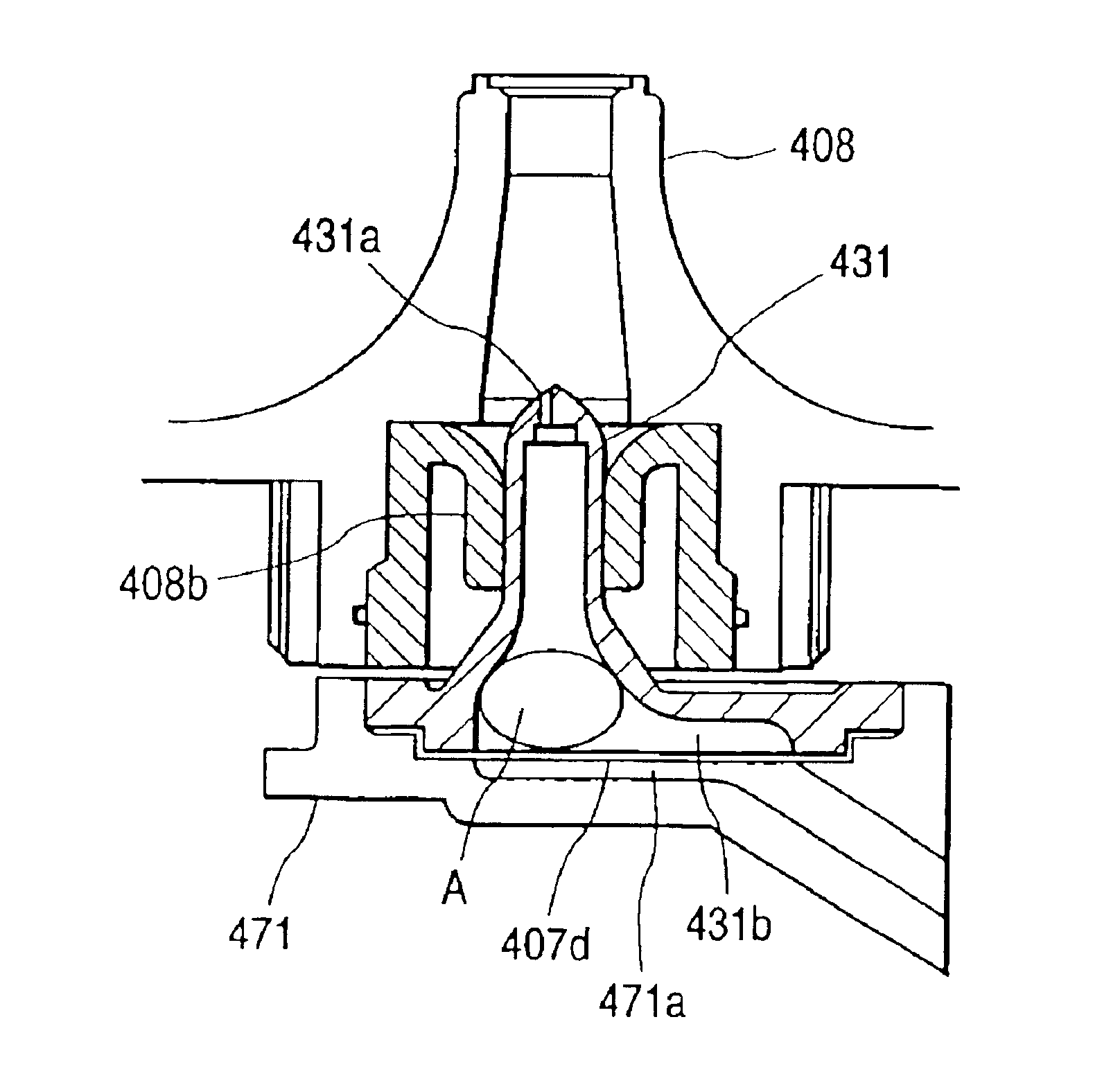
Next, the ink jet recording apparatus of the type shown in FIG. 1 using each ink cartridge mounted on the carriage as the ink storage section and comprising a preferred valve unit will be discussed.

That is, the valve unit in the embodiment dissolves the following problems of the valve unit in the related art: Since a shaft is inserted into an ink flow passage and is rotated, a gap occurs in any part other than the ink flow passage and desired negative pressure cannot be provided; because of recent tendency to increase the number of nozzle orifices, the suction pump has an insufficient capability to provide desired negative pressure; and the like.

Since the valve unit in the related art comprises O-rings used to enable rotation of the shaft inserted so as to cross the ink flow passage and retain the hermetic state, when the shaft is rotated, a large torque is required and a high-capability drive motor is required.

Consequently, the ink jet recording apparatus having the valve unit in t...

sixth embodiment

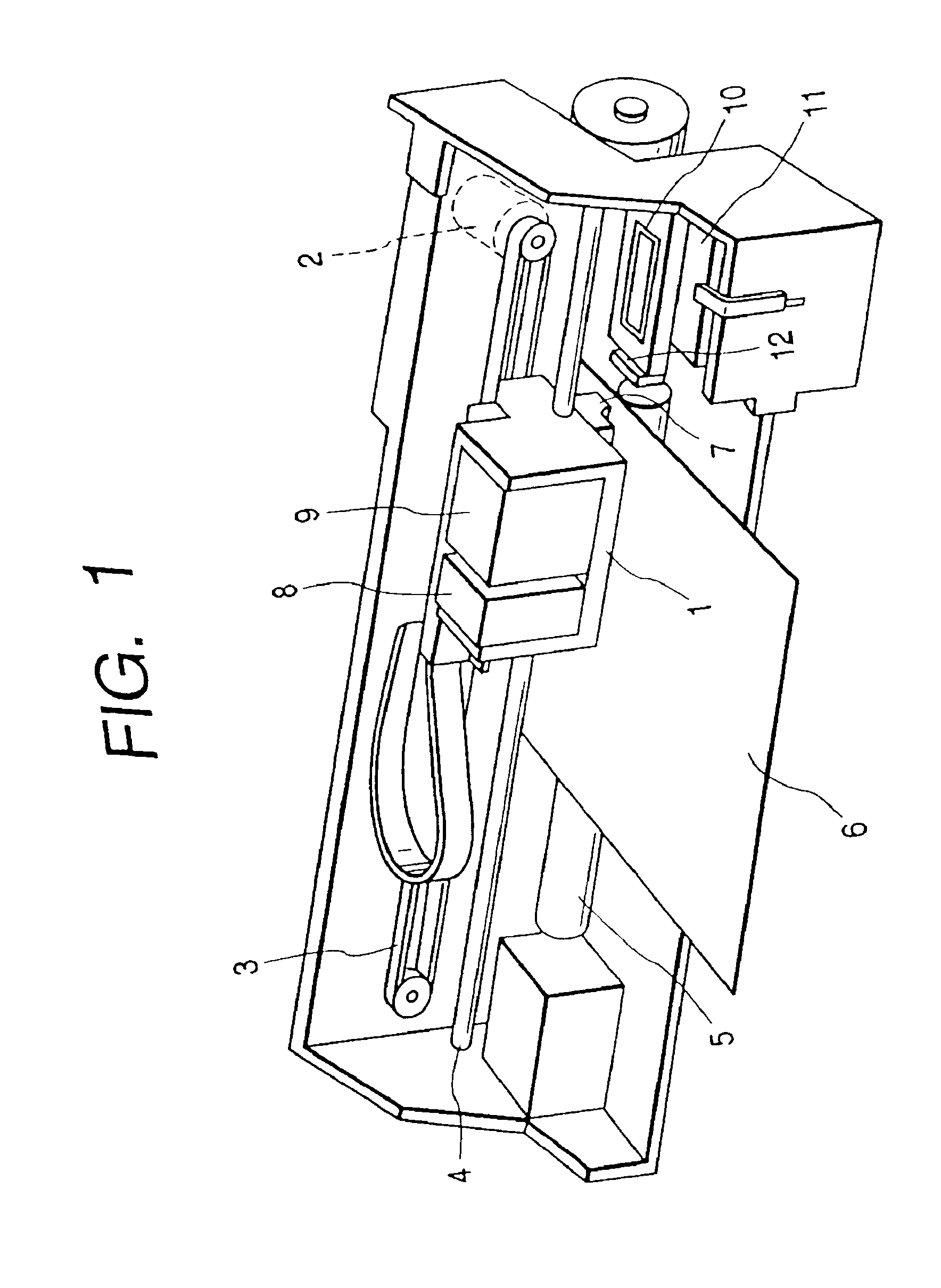
FIG. 23 is a plan view to show the ink jet recording apparatus of the type that can incorporate the invention.

In the figure, numeral 1 denotes a carriage. The carriage 1 is driven via a timing belt 3 by a carriage motor 2 and can be reciprocated in the length direction of a paper feed member 5 through a guide shaft 4.

An ink jet recording head 106 is mounted on the side of the carriage 1 facing recording paper 6.

Subtanks 107 as ink storage sections for supplying ink to the recording head 106 are placed on the carriage 1.

In the embodiment, four subtanks 107 are provided in a one-to-one correspondence with black, yellow, magenta, and cyan inks to temporarily store the inks in the subtanks.

Black, yellow, magenta, and cyan inks are supplied to the subtanks 107 from main tanks 108 to 111 as ink cartridges placed at the end of the recording apparatus via tubes 112.

On the other hand, a capping unit 113 for sealing the nozzle formation face of the recording head 106 is placed in a non-print ...


PUM


Abstract

A valve unit 36 is placed in an ink flow passage 35 between an ink cartridge 8 and a recording head 7 and can be controlled in association with the cleaning operation of the recording head 7. Under the control of a drive controller, the valve unit 36 holds for a predetermined time a state in which negative pressure produced by a suction pump is accumulated, and is opened after the expiration of the predetermined time or is opened with the negative pressure accumulated and driving the suction pump is continued. The air bubbles remaining in a stuck state in the ink flow passage can be peeled from the ink flow passage together with an instantaneous fast ink flow produced as the valve unit 36 is opened, and the peeled air bubbles can be discharged effectively from the ink flow passage following the subsequent ink flow.

Description

BACKGROUND OF THE INVENTIONThis invention relates to an ink jet recording apparatus comprising a recording head moving in a width direction of recording paper for jetting ink drops toward recording paper based on print data, thereby printing an image on the recording paper and a control technique of cleaning of the recording head for sucking ink from nozzle orifices of the recording head of the recording apparatus for recovering the print function of the recording head.An ink jet recording apparatus, which produces comparatively small noise at the printing time and moreover can form small dots at a high density, is much used for printing including color printing in these days.Such an ink jet recording apparatus comprises an ink jet recording head for receiving supply of ink from an ink storage section of an ink cartridge mounted on a cartridge, a subtank, etc., and paper feeder for causing recording paper to make a relative move to the recording head. While moving the recording head...

Claims


Application Information

Patent Timeline
IPC IPC(8): B41J2/17B41J2/19B41J2/165
CPCB41J2/19B41J2/16532
Inventor HARADA, SHUHEIMIYAZAWA, HISASHIHAYAKAWA, HITOSHIKOBAYASHI, ATSUSHIKIMURA, HITOTOSHIARUGA, YOSHIHARU
Owner SEIKO EPSON CORP
Why Eureka
Try Eureka