Interlock tabs for laminations

a technology of interlocking tabs and laminations, which is applied in the direction of transformer/inductance details, dynamo-electric machines, magnetic circuit shapes/forms/construction, etc., can solve the problems of loss of stack integrity, production must be stopped, and lamination may come, so as to eliminate the need for additional tooling

Inactive Publication Date: 2005-01-25
GENERAL ELECTRIC CO
View PDF14 Cites 34 Cited by
  • Summary
  • Abstract
  • Description
  • Claims
  • Application Information

AI Technical Summary

Benefits of technology

Accordingly, the system of the present invention provides for interlocking the upper lamination in a stack to the lowest lamination in the stack such that a tab of the upper lamination is inserted in an opening in the lower lamination(s) and then bent so tha

Problems solved by technology
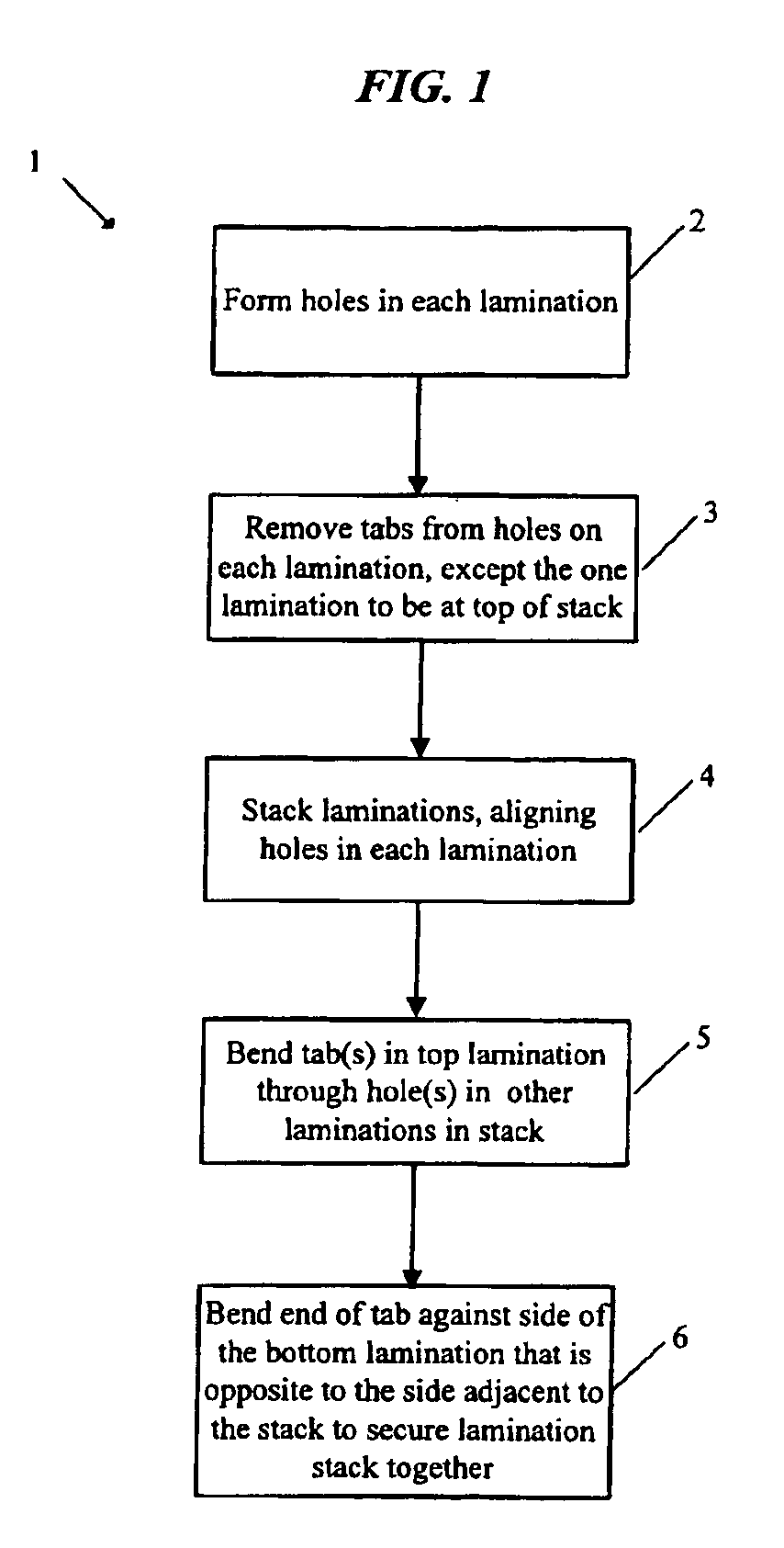
A drawback with the foregoing method of securing laminations together is that sometimes, in the course of further processing of the laminations, a lamination may come out of the slot on the next lower lamination.
When this happens, the integrity of the stack is lost, and production must be stopped to

Method used


Image

  • Interlock tabs for laminations
  • Interlock tabs for laminations
  • Interlock tabs for laminations

Examples


Embodiment Construction

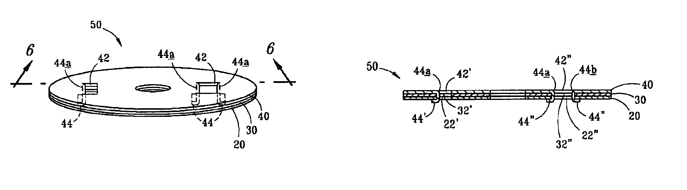
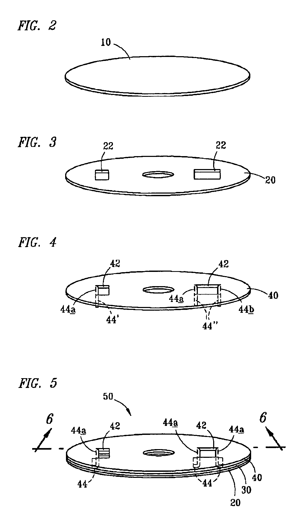
In the discussion of the FIGURES, the same reference numerals will be used throughout to refer to the same or similar components. In the interest of conciseness, various other components known to the art, such as dies, punches, and the like necessary for the manufacture of laminations, have not been shown or discussed. Even though numerous characteristics and advantages of the present invention have been described in the drawings and accompanying text, the description is illustrative only, and changes may be made, especially in matters of arrangement, shape and size of the parts, within the principles of the invention to the full extent indicated by the broad general meaning of the terms used in the claims. The words “top,”“uppermost,”“bottom,” and “lowermost,” as used in this document, are used in reference to a stack of laminations as it would appear when it is placed on a horizontal surface and the lamination to which an interlock tab is attached is at the “top,” or furthest away...


PUM


Abstract

A laminated plate assembly in which the laminations in a stack are secured together by means of one or more interlocks or tabs that project from the uppermost lamination in the assembly through holes or slots in all the other laminations in the assembly, or around the periphery of the other laminations in the assembly, with each tab being bent or pressed against the underside of the bottom lamination in the assembly. This secures all the laminations in the stack together, much like a staple secures papers in a stack together, allowing for additional handling and processing of the laminated plate assembly without concern that the laminated plates in the stack will become misaligned or even become removed from the stack.

Description

BACKGROUND OF INVENTIONThis invention relates generally to interlocking laminations used in electrical devices, such as those used in the windings for D.C. motor armatures or A.C. rotors and stators.Typically, laminations are stacked, or piled together to achieve a required thickness of laminations. Because the laminations undergo further processing, such as being wound to form a motor core, it is desirable to retain the laminations together in a stack of a desired height so that the stack of laminations can be moved together to a subsequent manufacturing process.Various methods and apparatuses have been used to fasten laminations together, including the use of tabs in the laminations which extend below the lower surface of the lamination and are inserted into a slot formed in a next adjacent lamination. Typically, the lowest lamination in the stack has the interlock tabs removed because there is no need to secure the lowest lamination in the stack to anything else.A drawback with t...

Claims


Application Information

Patent Timeline
IPC IPC(8): H01F3/00H01F3/02H02K1/06H01F27/245
CPCH01F3/02H02K1/06H02K2201/09H01F27/2455
Inventor SIROIS, ROBERTHOLICH, JAMES J.BOBAY, DENNIS P.HOLLENBECK, ROBERT K.HALL, JEFFREY A.
Owner GENERAL ELECTRIC CO
Why Eureka
Try Eureka