Electric power meter including a temperature sensor and controller

a technology of temperature sensor and electric power meter, which is applied in the direction of fire alarms, instruments, and using reradiation, etc., can solve the problems of damage to the customer premises and injury or death of persons

Inactive Publication Date: 2005-01-25
MOTOROLA SOLUTIONS INC
View PDF13 Cites 70 Cited by
  • Summary
  • Abstract
  • Description
  • Claims
  • Application Information

AI Technical Summary

Problems solved by technology

This heat can affect the reliability of the power measurement apparatus within the electric power meter ...

Method used


Image

  • Electric power meter including a temperature sensor and controller
  • Electric power meter including a temperature sensor and controller
  • Electric power meter including a temperature sensor and controller

Examples


Embodiment Construction

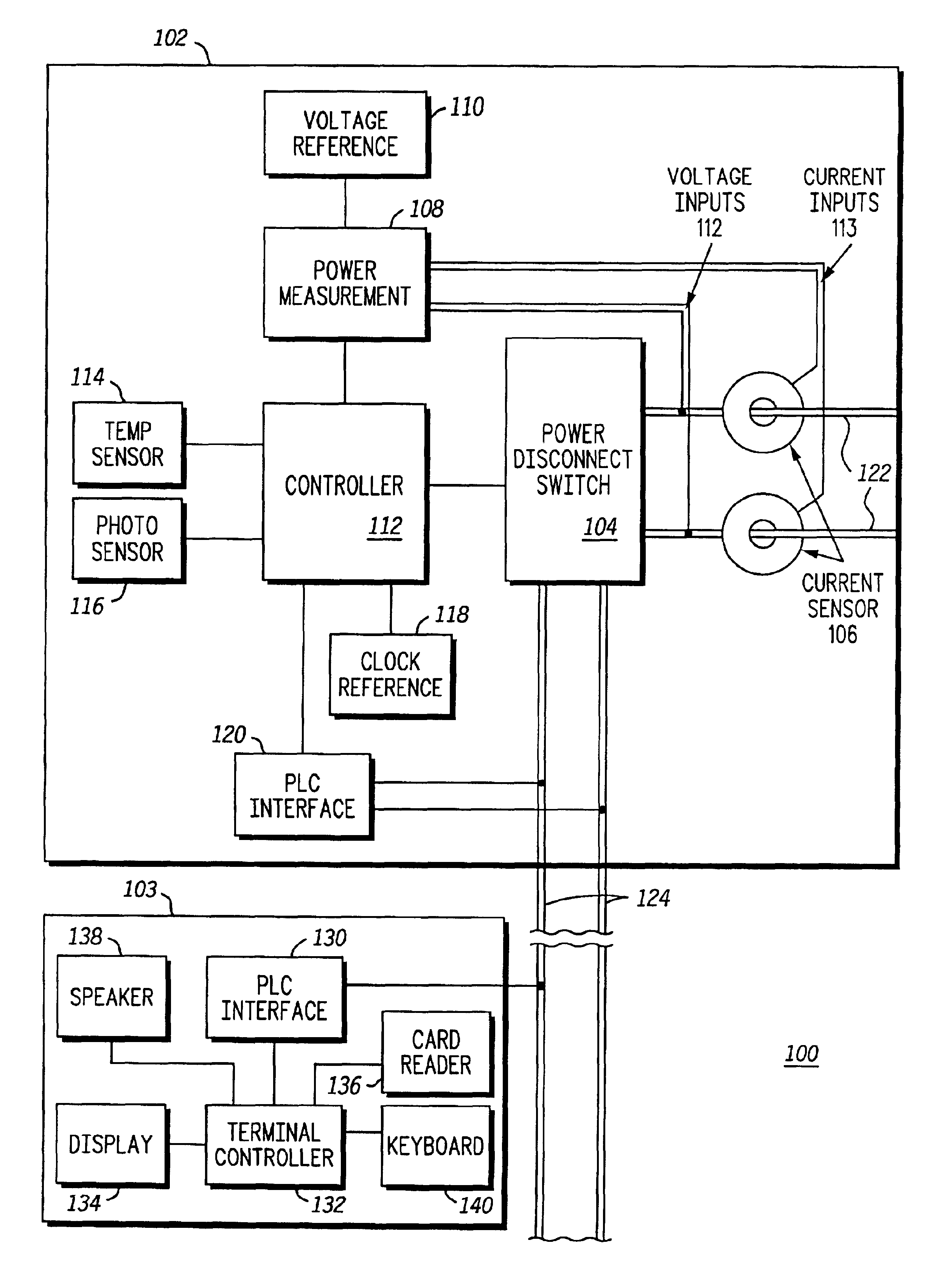
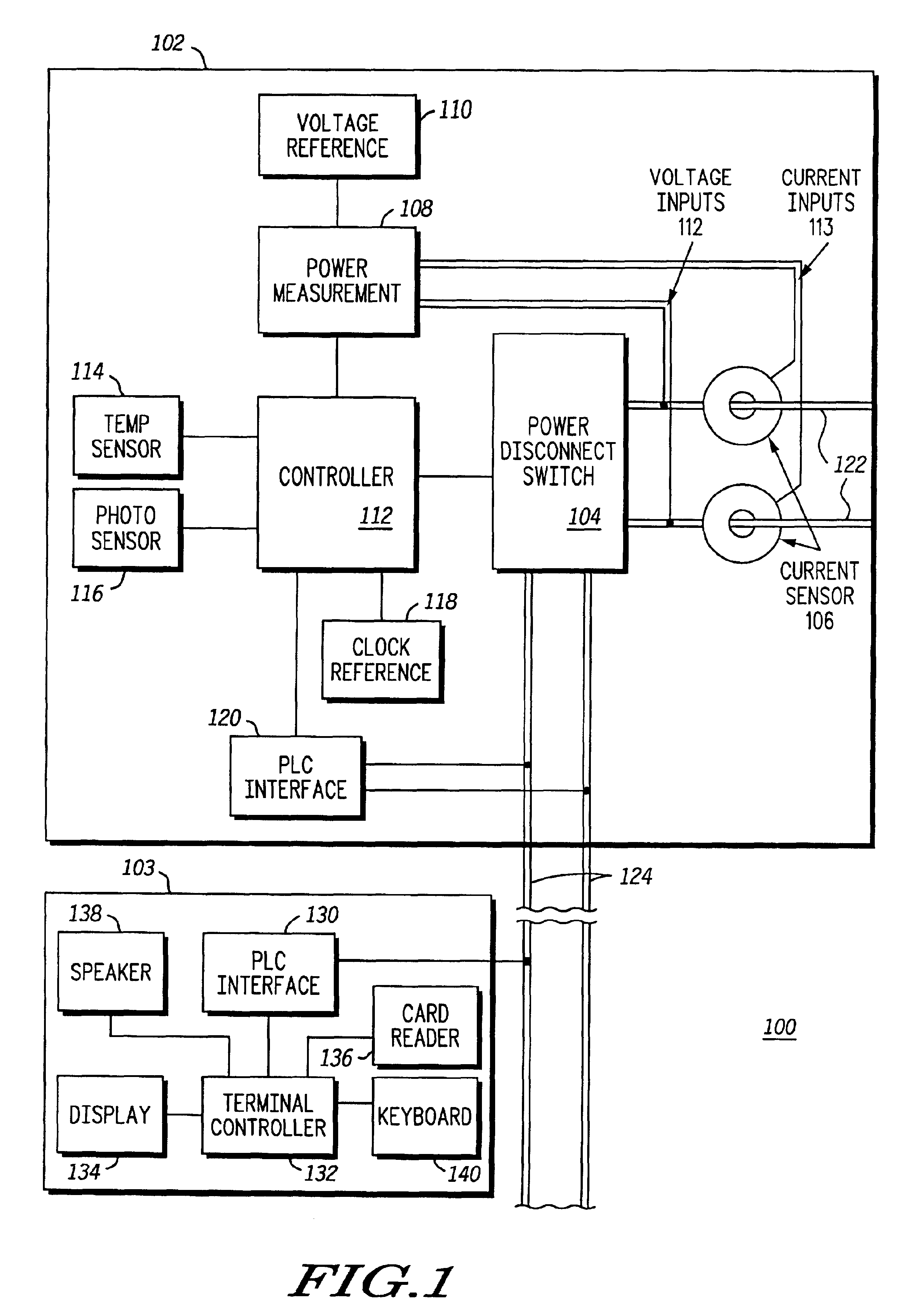
FIG. 1 illustrates an electric energy metering system 100 according to the present invention. The electric energy metering system 100 is adapted to measure the amount of electrical energy used within a customer premises such as a house, apartment, commercial building or factory. Further, according to principles of the present invention, the electric energy metering system is adapted to shut off power when temperature conditions dictate to reduce the likelihood of fires; and to comply with regulatory rules when disconnecting power for non-payment of energy charges. Generally, the electric energy metering system 100 comprises an electric metering device (“power meter”) 102 and a customer terminal 103. Typically, the power meter 102 is installed exterior to the customer premises and the customer terminal 103 is within the customer premises.

The power meter 102 measures the amount of electrical power being used by a customer. In one embodiment, the power meter 102 comprises a power disco...


PUM


Abstract

An electric power meter (102) includes a temperature sensor (114) and a controller (112). The controller (112) is operable, based on the temperature reported from the temperature sensor (114), to generate alarm(s) when the temperature exceeds certain alarm threshold(s) (307, 507, 508) and to activate a power disconnect switch (104), thereby shutting off power to a customer premises, when the temperature exceeds a shut off threshold (309, 509). The controller (112) is operable to activate the power disconnect switch (104) for non-payment of electricity cost, subject to secondary criteria based on regulatory requirements. A customer terminal (103) may be used to notify a customer of an alarm condition, to provide information regarding electrical power usage or to provide information regarding disconnection of electrical power.

Description

FIELD OF THE INVENTIONThis invention relates generally to electric power meters and more particularly to an electric power meter that contains a temperature sensor and a controller.BACKGROUND OF THE INVENTIONElectric power meters are well known devices used by utility service providers for measuring the amount of electrical power consumed by a residential or industrial customer. At the lower end of complexity, power meters consist simply of a power measurement apparatus for measuring power consumption and a gauge that is visible on the outside of the power meter for showing the amount of electrical power consumed. Customers are billed by the utility companies based on periodic readings of the electric power meter, indicating electrical power already used. More recently, prepayment utility metering systems have become known in which the customer pays for the electricity at the electric power meter in advance, before it is used. Oftentimes, in prepayment systems, power can be disconne...

Claims


Application Information

Patent Timeline
IPC IPC(8): H04Q9/02
CPCG01D3/08H04Q9/02H04Q2209/30H04Q2209/823H04Q2209/60
Inventor YEE, DAVID MOONZUCARELLI, PHILIP JOHNKELLER, THEODORE WOOLLEYWALLIS, DAVID RICHARD
Owner MOTOROLA SOLUTIONS INC
Why Eureka
Try Eureka