Switch-variable optical attenuator and switch arrays

a technology of variable optical attenuator and switch array, which is applied in the field of optical systems, can solve the problems that the current attenuation and switching techniques do not address the problem of fast and accurate switching and attenuation

Inactive Publication Date: 2005-01-25
RPX CLEARINGHOUSE
View PDF2 Cites 4 Cited by
  • Summary
  • Abstract
  • Description
  • Claims
  • Application Information

AI Technical Summary

Benefits of technology

Yet another object of the present invention is to provide a novel method for attenuating a light signal in an optical system.

Problems solved by technology

Attenuation and switching techniques that exist in the art do not address the problem of fast and accurate switching and attenuation combined with ease of implementation.

Method used


Image

  • Switch-variable optical attenuator and switch arrays
  • Switch-variable optical attenuator and switch arrays
  • Switch-variable optical attenuator and switch arrays

Examples


Embodiment Construction

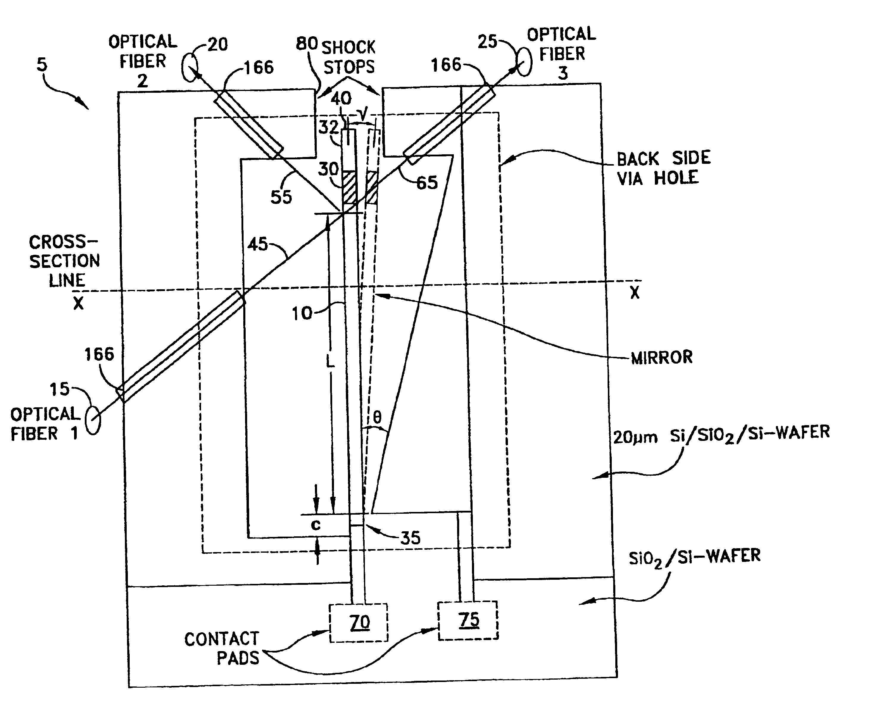
Referring to FIG. 1, there is schematically shown a switch and variable optical attenuator 5 with an input fiber 6, a first output fiber 7 and a second output fiber 8. A transmitter device 6a is attached to input fiber 6. Receiver devices 7a, 8a are attached to output devices 7, 8, respectively. In a preferred embodiment, switch and variable optical attenuator 5 switches a light beam 9, emitted by transmitter device 6a through input fiber 6, between receiver devices 7a, 8a coupled with first output fiber 7 and second output fiber 8, respectively. Additionally, switch and variable optical attenuator 5 may switch light beam 9 traveling from receiver devices 7a, 8a to transmitter device 6a. Alternatively, receiver devices 7a, 8a may comprise a single device with two separate receivers. In another preferred embodiment, switch and variable optical attenuator 5 attenuates light beam 9 as it is switched between first output fiber 7 and second output fiber 8.

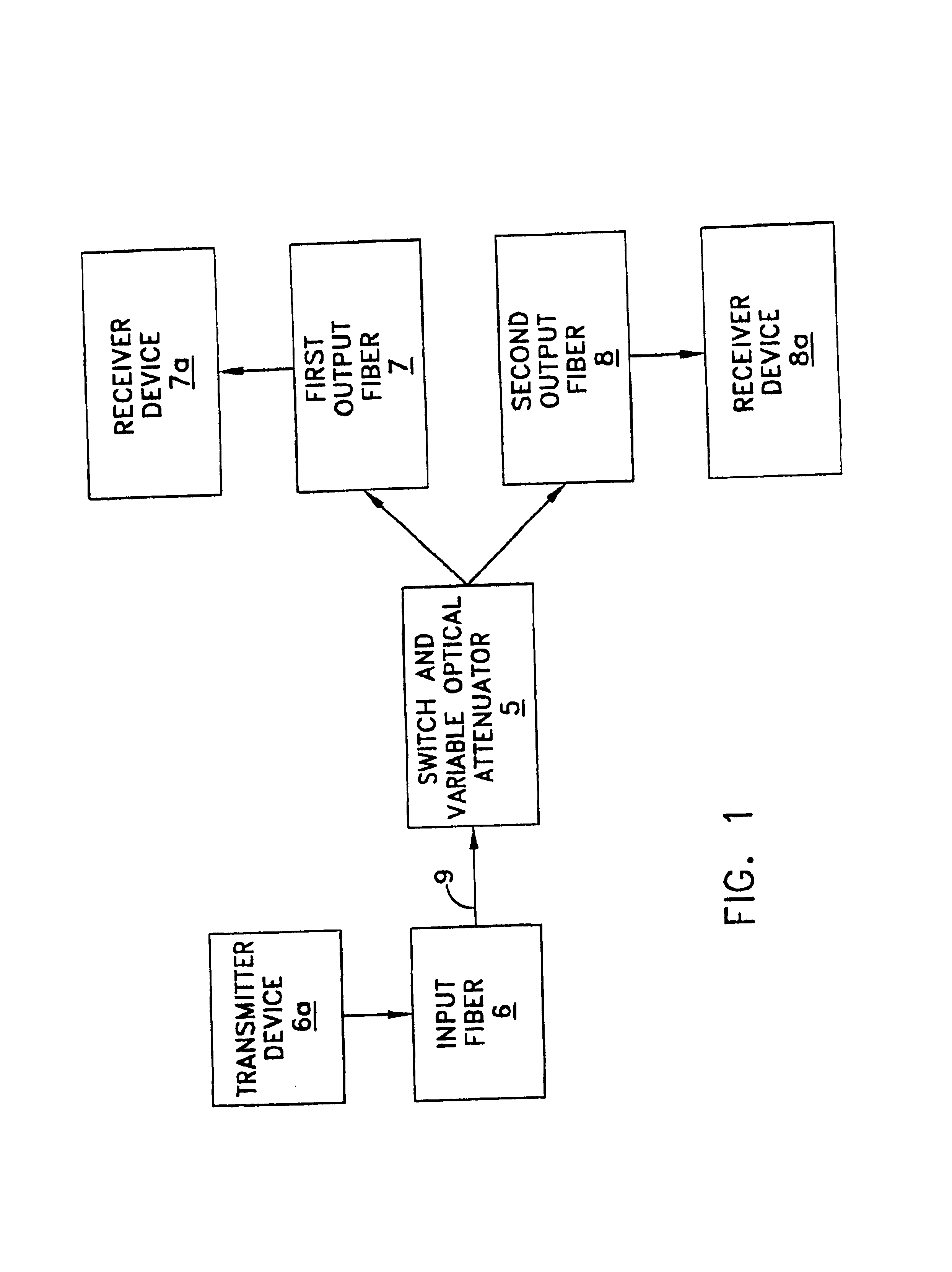
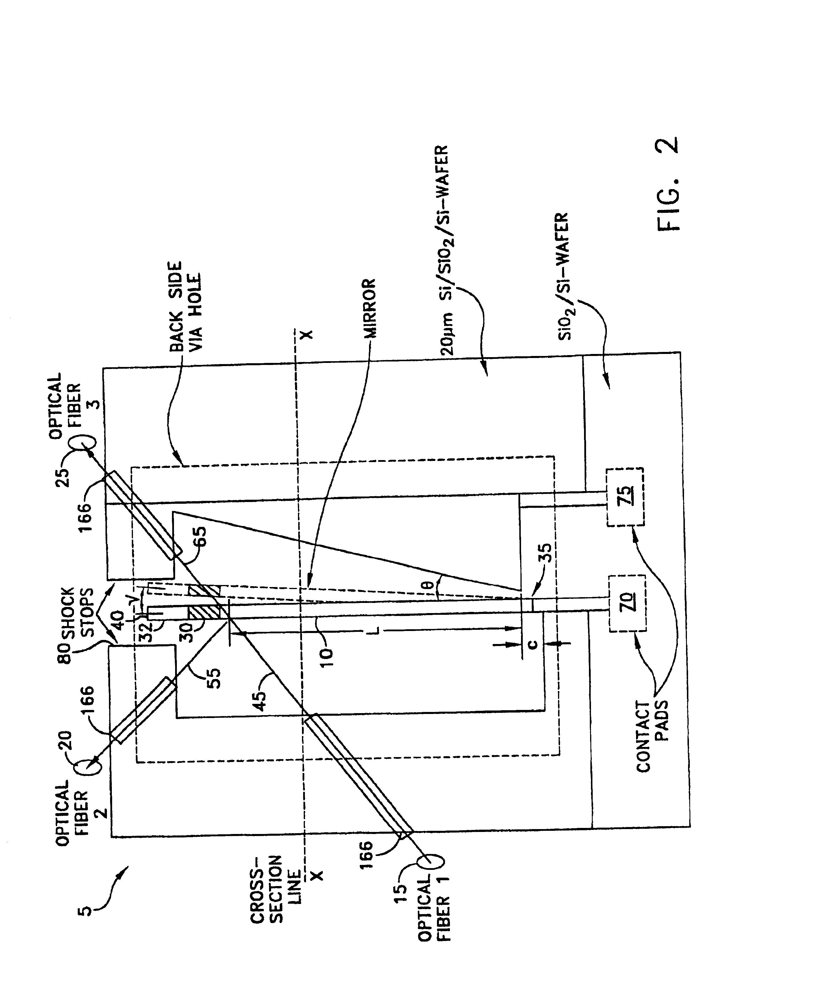
Looking now at FIG. 2, there is ...


PUM


Abstract

Novel light switches and attenuators are disclosed. In one form of the invention, a novel 1×2 switch is formed by positioning a moveable cantilever mirror having an opening intermediate three fiberoptic lines. In another form of the invention, a novel n×n switch is formed by positioning a moveable cantilever mirror having n openings intermediate n sets of three fiberoptic lines. In still another form of the invention, a novel variable optical attenuator is formed by incrementally positioning a moveable cantilever mirror having an opening intermediate a set of three fiberoptic lines.

Description

FIELD OF THE INVENTIONThis invention relates to optical systems in general, and more particularly to switches and attenuators for use in optical systems.BACKGROUND OF THE INVENTIONIn many situations, it is necessary to switch or attenuate an optical signal that is transmitted within an optical system.By way of example but not limitation, in a typical optical system, it may be necessary to switch or attenuate an optical signal between a first line (e.g., a fiberoptic or fiber line) and a second line (e.g., a fiberoptic or fiber line).Attenuation and switching techniques that exist in the art do not address the problem of fast and accurate switching and attenuation combined with ease of implementation.SUMMARY OF THE INVENTIONOne object of the present invention is to provide novel apparatus for switching a light signal in an optical system.Another object of the present invention is to provide novel apparatus for attenuating a light signal in an optical system.Still another object of th...

Claims


Application Information

Patent Timeline
Patent Type & Authority Patents(United States)
IPC IPC(8): G02B6/26G02B6/35
CPCG02B6/266G02B6/3566G02B6/3518G02B6/3546G02B6/3598G02B6/357G02B6/3594G02B6/355
Inventor ABU-AGEEL, NAYEF M.
Owner RPX CLEARINGHOUSE
Why Eureka
Try Eureka