Display panel capable of fingerprint identification

a display panel and fingerprint identification technology, applied in the field of display screens, can solve the problems of low screen-to-body ratio or very complicated design, and achieve the effects of improving fingerprint identification capability, enhancing screen-to-body ratio, and enhancing reflected light signals received

Active Publication Date: 2020-07-21
WUHAN CHINA STAR OPTOELECTRONICS SEMICON DISPLAY TECH CO LTD
View PDF16 Cites 1 Cited by
  • Summary
  • Abstract
  • Description
  • Claims
  • Application Information

AI Technical Summary

Benefits of technology

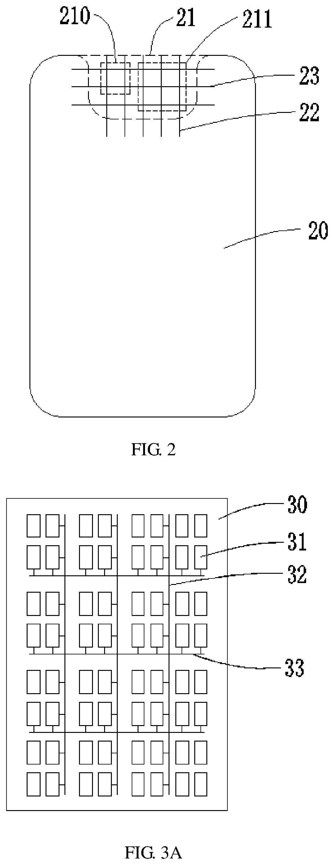
[0004]The disclosure proposes a display panel having fingerprint identification. Fingerprint identification technology can be integrated into an irregular area of the display panel without irregular cutting. Not only the yield rate is ensured but also the screen-to-body ratio is enhanced.
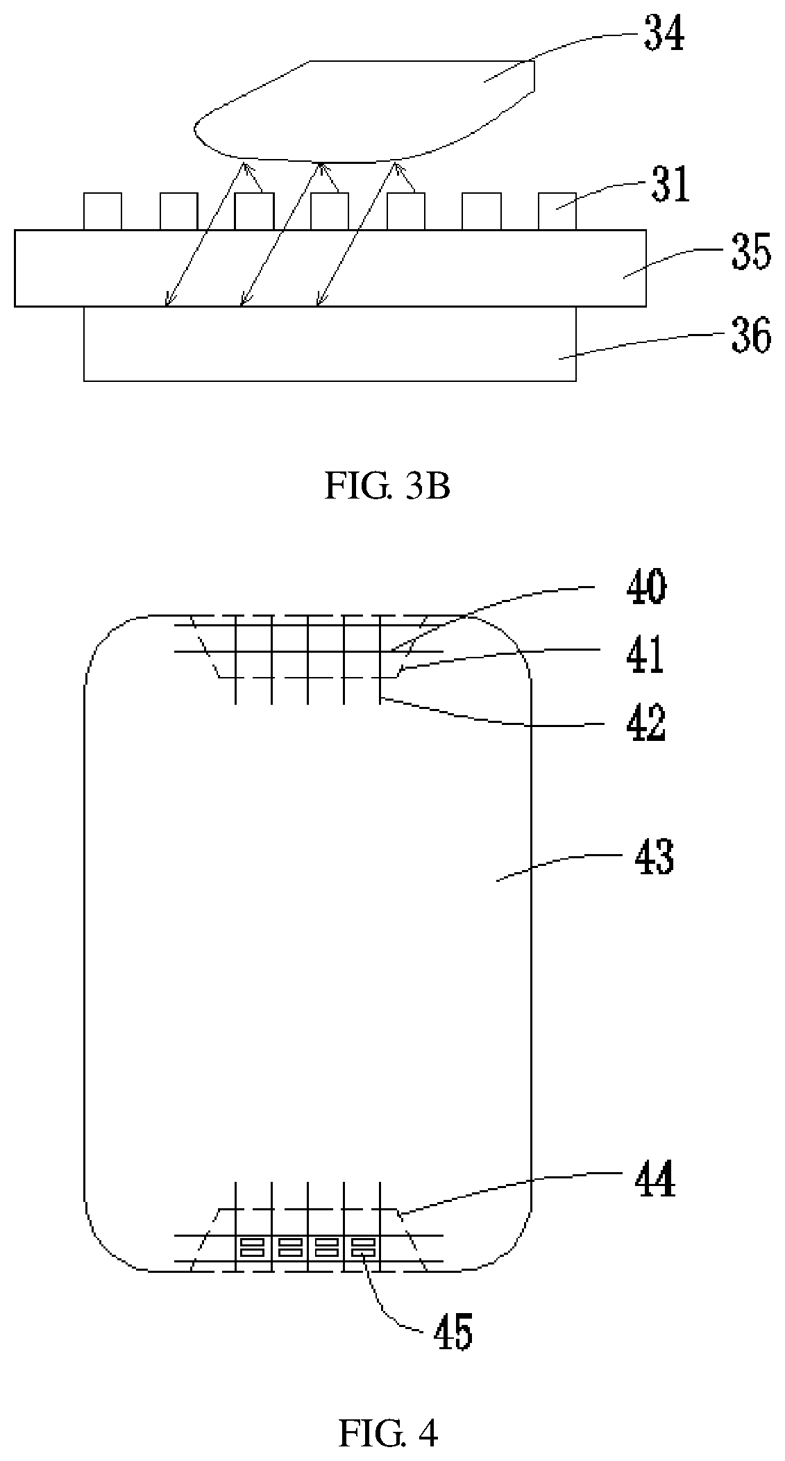
[0011]According to one embodiment of the present disclosure, some of the dummy pixels in the fingerprint identification cue area is configured to illuminate to strengthen a reflected light signal received by the fingerprint identification module.
[0015]The present disclosure which proposes the display panel having fingerprint identification brings benefits that the screen-to-body ratio is enhanced by integrating the fingerprint identification technology into the non-display area (irregular area), that the unbalanced illumination of the display panel is improved by remaining the non-display area uncut and arranging low-density dummy pixels, the data lines, and the gate lines in the non-display area. In addition, some of the dummy pixels in the fingerprint identification cue area can be configured to illuminate, which helps to enhance reflected light signals received by the fingerprint identification module and to improve the fingerprint identification capability.

Problems solved by technology

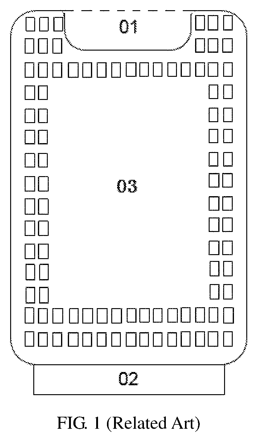
However, such a design causes unbalanced illumination due to the resistor-capacitor (RC) loading around the U-shaped area 01, and the irregular cutting itself is liable to produce undesirable results.
In addition, a fingerprint identification module in a cellphone of the related art is designed under the display panel (such as the fingerprint identification area 02 in FIG. 1) or the back of the cellphone, which may cause a problem like relatively low screen-to-body ratio or very complicated design.

Method used


Image

  • Display panel capable of fingerprint identification
  • Display panel capable of fingerprint identification
  • Display panel capable of fingerprint identification

Examples


Embodiment Construction

[0023]In the disclosure, it is should be understood that spatially relative terms, such as “center”, “longitudinal”, “lateral”, “length”, “width”, “above”, “below”, “front”, “back”, “left”, “right”, “horizontal”, “vertical”, “top”, “bottom”, “inner”, “outer”, “clockwise”, “counterclockwise”, “axial”, “radial”, “circumferential”, and the like, may be used herein for ease of description to describe one element or feature's relationship to another element(s) or feature(s) as illustrated in the figures. It will be understood that the spatially relative terms are intended to encompass different orientations of the device in use or operation in addition to the orientation depicted in the figures. The spatially relative terms are not limited to specific orientations depicted in the figures. In addition, the term “first”, “second” are for illustrative purposes only and are not to be construed as indicating or imposing a relative importance or implicitly indicating the number of technical fe...


PUM


Abstract

A display panel capable of fingerprint identification includes a base substrate, a TFT layer, a pixel unit, and a dummy pixel. The base substrate includes a display area and a non-display area. The dummy pixel is formed on the TFT layer where the pixel unit is arranged as well, and distributed in the non-display area. The non-display area comprises a fingerprint identification cue area configured to transmit fingerprint information to a fingerprint identification module. The fingerprint identification module is arranged on one side of the TFT layer facing away from the dummy pixel. When a finger touches the fingerprint identification cue area, a light is emitted from the fingerprint identification cue area to the finger. The fingerprint identification module is configured to implement fingerprint identification based on the light that is reflected from a surface of the finger and passes through a gap between the dummy pixels.

Description

BACKGROUND1. Field of the Disclosure[0001]The present disclosure relates to the technical field of a display screen, and more particularly, to a display screen capable of fingerprint identification.2. Description of the Related Art[0002]An active-matrix organic light-emitting diode (AMOLED) display panel has gradually become the mainstream product in the next-generation display technology owing to their high contrast, wide color gamut, low power consumption, and foldability. In the field of cellphone display, to increase the screen-to-body ratio and to enlarge the display area, a cutting method called U-Cut for an irregular area is adopted in the panel technology of the related art. As illustrated in FIG. 1, the display panel includes a display area 03 and a non-display area. A U-shaped area 01 is cut from the non-display area on the upper portion of the display panel for placing an earpiece, a front camera, etc. However, such a design causes unbalanced illumination due to the resis...

Claims


Application Information

Patent Timeline
Patent Type & Authority Patents(United States)
IPC IPC(8): G06K9/00H01L27/32
CPCG06K9/0004H01L27/3223G06V40/1318H10K59/88H10K59/65
Inventor WU, SHAOJINGLI, SHUANG
Owner WUHAN CHINA STAR OPTOELECTRONICS SEMICON DISPLAY TECH CO LTD
Why Eureka
Try Eureka