Switch device

Inactive Publication Date: 2004-04-01
CHEN YI TING
View PDF5 Cites 0 Cited by
  • Summary
  • Abstract
  • Description
  • Claims
  • Application Information

AI Technical Summary

Problems solved by technology

However, when circuits in the switch frame fail to receive an input voltage, the switch can not work.
Furthermore, the LED is

Method used


Image

  • Switch device
  • Switch device
  • Switch device

Examples


Example

[0014] Wherever possible in the following description, like reference numerals will refer to like elements and parts unless otherwise illustrated.

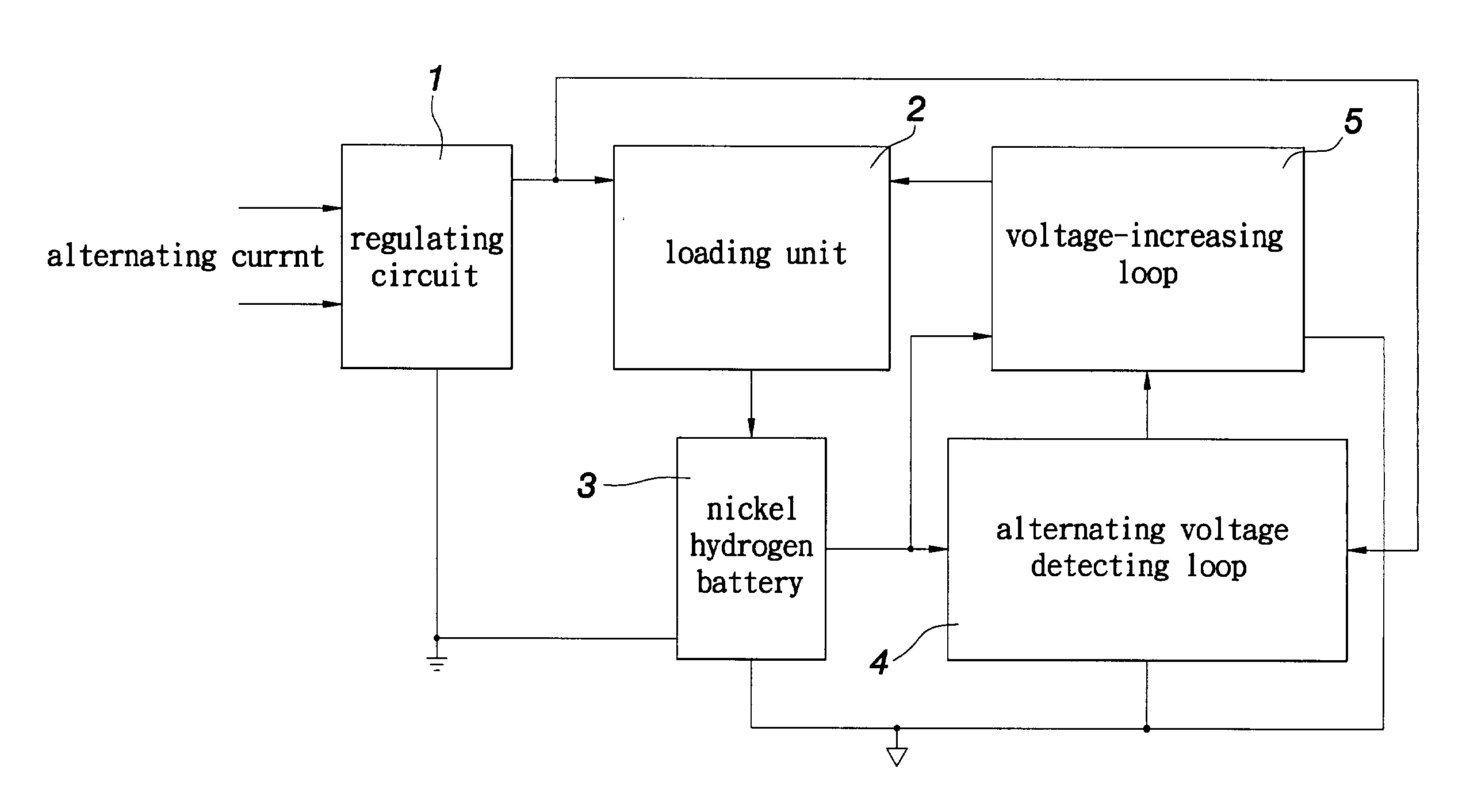
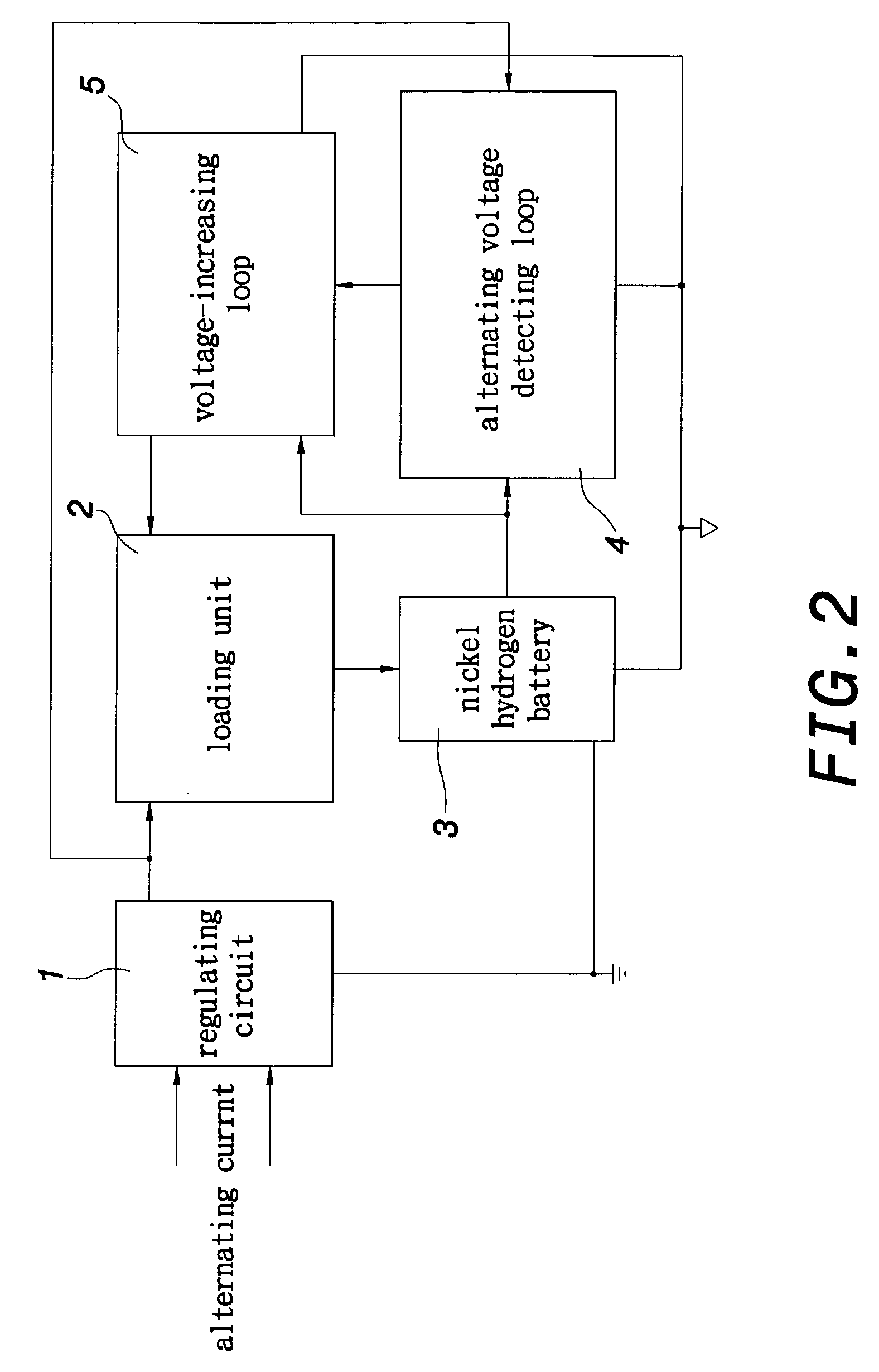
[0015] With reference to FIG. 2 and FIG. 3, a switch device according to the invention includes a regulating circuit 1, a loading unit 2, a battery 3, an alternating voltage detecting loop 4 and a voltage-increasing loop 5.

[0016] The regulating circuit 1 includes a plurality of capacitors C1 and C2, a plurality of regulators D1-D4 and a plurality of diodes D5 and D6. The regulating circuit 1 regulates an inputted alternating voltage such as 220 V or 110V.

[0017] The loading unit 2 is connected to an output terminal of the regulating circuit 1. According to one embodiment of the invention, the loading unit 2 is a switch frame 6 including a plurality of light emitters, such as light-emitting diodes (LED) L1-L6 connected in series, as shown in FIG. 4. Each of the LED L1-L6 emits a monochromatic or polychromatic light when receiving a voltage o...


PUM


Abstract

A switch device includes a regulating circuit, a loading unit, a battery, an alternating voltage detecting loop and a voltage-increasing loop. The regulating circuit serves to regulate an inputted alternating voltage. The loading unit is connected to an output terminal of the regulating circuit, and operates when receiving a voltage outputted from the regulating circuit. The battery is connected to an output terminal of the loading unit. The battery keeps charging while the loading unit is working. The alternating voltage detecting loop is respectively connected to the regulating circuit and the battery. The voltage-increasing loop is respectively connected to the alternating voltage detecting loop and the battery. When the alternating voltage detecting loop works, the voltage-increasing loop generates oscillation to increase the power of the nickel hydrogen battery and drive the loading unit.

Description

[0001] 1. Field of the Invention[0002] The invention relates to a switch device and, more particularly, to a switch device including a regulating circuit, a loading unit and an alternating voltage detecting loop. When the voltage from the regulating circuit can not be directly input to the loading unit, which is detected by the alternating voltage detecting loop, the voltage-increasing loop increases the power of the battery to keep the loading unit working.[0003] 2. Description of the Related Art[0004] FIG. 1 shows a conventional switch device having a light emitter. The conventional switch device includes silicon control regulator (SCR), a photosensitive resistor, a light emitting diode and resistors R1, R2 in a switch frame (not shown). When the photosensitve resistor does not receive any light, the SCR is at ON status to drive the LED.[0005] However, when circuits in the switch frame fail to receive an input voltage, the switch can not work. Furthermore, the LED is easily affect...

Claims


Application Information

Patent Timeline
IPC IPC(8): H05B44/00
CPCH05B33/0803Y02B20/346H05B33/0815Y02B20/30H05B45/3725
Inventor CHEN, YI TING
Owner CHEN YI TING
Why Eureka
Try Eureka