Optical fiber tube assembly having a plug

a technology of optical fiber tube and plug, which is applied in the direction of optics, fibre mechanical structures, instruments, etc., can solve the problems of thixotropic materials that must be removed, and water must still be blocked in the tube, so as to achieve the effect of preventing clogging of the tube and preventing clogging

Inactive Publication Date: 2005-01-25
CORNING OPTICAL COMM LLC
View PDF24 Cites 48 Cited by
  • Summary
  • Abstract
  • Description
  • Claims
  • Application Information

AI Technical Summary

Benefits of technology

The present invention is directed to a fiber optic tube assembly including a tube having a longitudinal axis, a ribbon stack, a first plug, and a second plug. The ribbon stack includes at least one optical fiber ribbon, and the ribbon stack being at least partially disposed within the tube and being rotated therein. A first plug is disposed within the tube at a first predetermined location with a portion of the ribbon stack being disposed within the first plug. The first plug generally inhibits the rotation of the ribbon stack relative to the tube at the predetermined first location. The second plug is disposed within the tube at a second predetermined location with a portion of the ribbon stack being disposed within the second plug. The second plug generally inhibits the rotation of the ribbon stack relative to the tube at the predetermined second location. Additionally, the ribbon stack has at least one-hundred and eighty degrees of rotation between the first plug and the second plug, and a portion of the ribbon stack disposed within one of the plugs is capable of moving about the longitudinal axis relative to at least one of the plugs.

Problems solved by technology

However, the thixotropic materials are messy and must be removed before the craftsman can optically connect optical waveguides of the optical ribbons.
Consequently, “dry tube” designs have removed the thixotropic materials from the tube, but water must still be blocked in the tube.
However, conventional dry tubes have disadvantages.
One disadvantage of this design is that voids are formed between the optical fibers, the tube wall, and the water-swellable materials along the length of the tube.
However, effective coupling requires a substantial amount of water-swellable material that adds expense, thereby increasing cable-manufacturing costs.

Method used


Image

  • Optical fiber tube assembly having a plug
  • Optical fiber tube assembly having a plug
  • Optical fiber tube assembly having a plug

Examples


Embodiment Construction

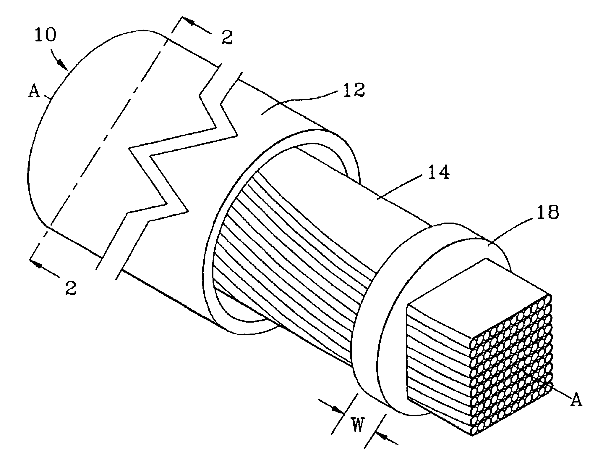
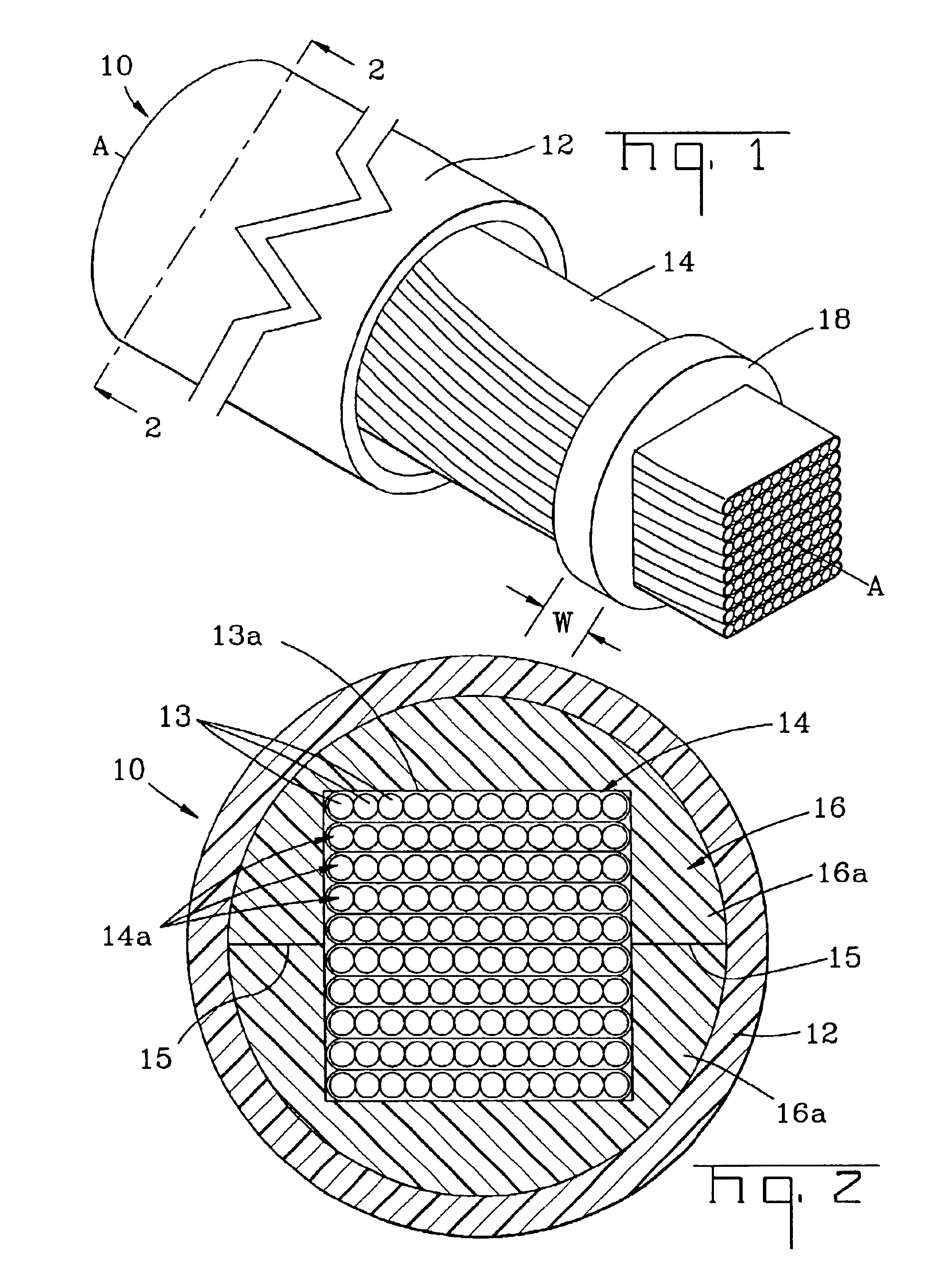
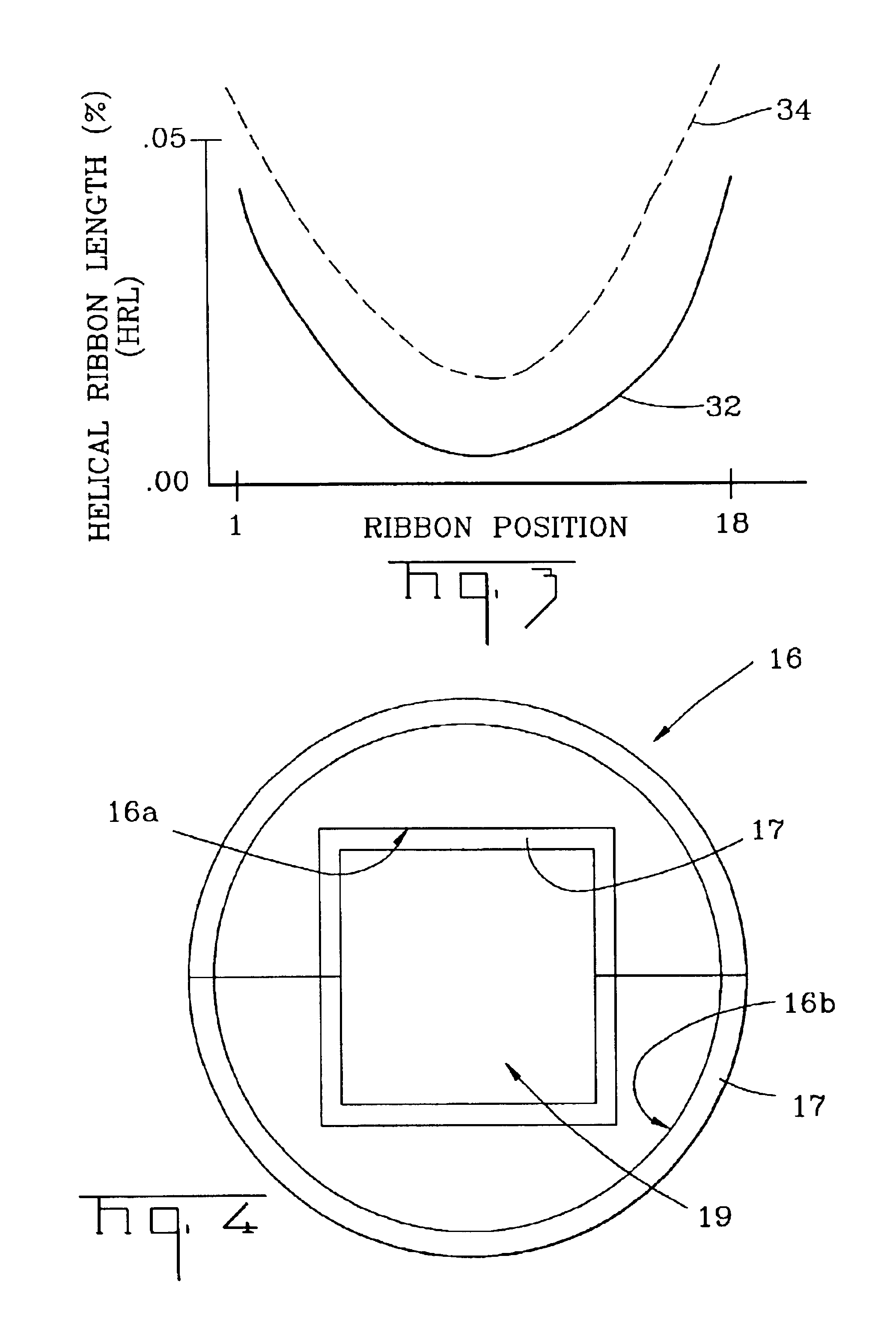
Illustrated in FIGS. 1 and 2 is an exemplary section of fiber optic tube assembly 10 that includes a tube 12, at least one optical fiber, for instance, a ribbon stack 14, and at least one plug. The plugs of the present invention are discrete plugs that are individually locatable so that the tube assembly has sections without a portion of a plug assembly, rather than requiring a water swellable tape having plugs attached thereto and surrounding the same. Tube 12 has a longitudinal axis A—A extending along its length and a first plug 16 (not visible in FIG. 1) and a second plug 18 that are operable to inhibit the migration of water along tube 12. Ribbon stack 14 is at least partially disposed within tube 12 and is twisted therein with a predetermined lay length during manufacture. First plug 16 is disposed within tube 12 at a first predetermined location and second plug 18 is disposed within tube 12 at a second predetermined location with successive plugs following as needed. A portio...


PUM


Abstract

A fiber optic tube assembly including a tube having a longitudinal axis, at least one optical fiber, and at least one plug. The at least one optical fiber being at least partially disposed within the tube and the at least one plug being disposed within the tube at a predetermined location. A portion of the at least one optical fiber disposed within the at least one plug is capable of moving about the longitudinal axis of the tube relative to at least one plug. In other embodiments, the at least one plug includes an interfacial layer.

Description

FIELD OF THE INVENTIONThe present invention relates generally to fiber optic cables. More specifically, the invention relates to a fiber optic tube assembly having at least one plug.BACKGROUND OF THE INVENTIONFiber optic ribbons include optical waveguides such as optical fibers that transmit optical signals such as voice, video, and / or data information. Fiber optic ribbons generally have a plurality of adjacent optical fibers arranged in a generally planar array in a matrix material. Additionally, the fiber optic ribbons can be arranged as a ribbon stack for a relatively high optical fiber-density.One optical fiber cable design employing a ribbon stack places the same into a tube filled with a thixotropic material such as grease. Thixotropic materials are used because they are effective at blocking the migration of water inside the tube. Additionally, thixotropic materials function as a friction element inhibiting substantial ribbon stack movement when the fiber optic cable is insta...

Claims


Application Information

Patent Timeline
Patent Type & Authority Patents(United States)
IPC IPC(8): G02B6/44
CPCG02B6/4405G02B6/4411
Inventor LAIL, JASON C.LARSON, PAUL A.
Owner CORNING OPTICAL COMM LLC
Why Eureka
Try Eureka