Alternative method to cementing casing and liners

a technology of casing and cement, which is applied in the direction of drilling casings, drilling pipes, borehole/well accessories, etc., can solve the problems of equipment occupying significant space, requiring special equipment and specially trained personnel, and expensive procedures

Inactive Publication Date: 2005-02-01
BAKER HUGHES OILFIELD OPERATIONS LLC
View PDF12 Cites 133 Cited by
  • Summary
  • Abstract
  • Description
  • Claims
  • Application Information

AI Technical Summary

Problems solved by technology

This procedure is expensive and requires the use of specialized equipment and specially trained personnel.
The process is time consuming and the equipment takes up significant space such that in offshore platforms careful logistics are required to make room for the equipment when the cementing job is required.
There are also uncertainties as to the distribution of the cement causing concerns of channeling of fluids from one zone penetrated by the casing or liner to an adjacent zone.
The grout design is not workable for the fluids and temperatures typically seen in oil and gas wells.

Method used


Image

  • Alternative method to cementing casing and liners
  • Alternative method to cementing casing and liners
  • Alternative method to cementing casing and liners

Examples


Embodiment Construction

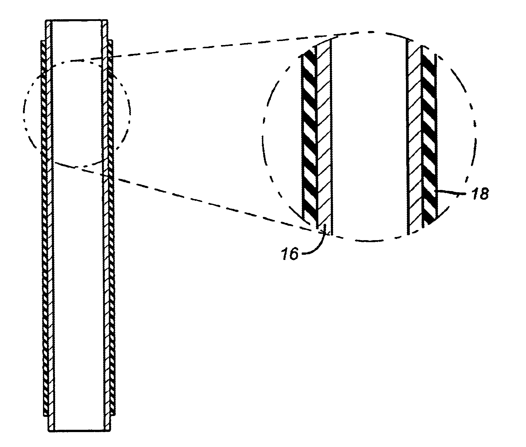
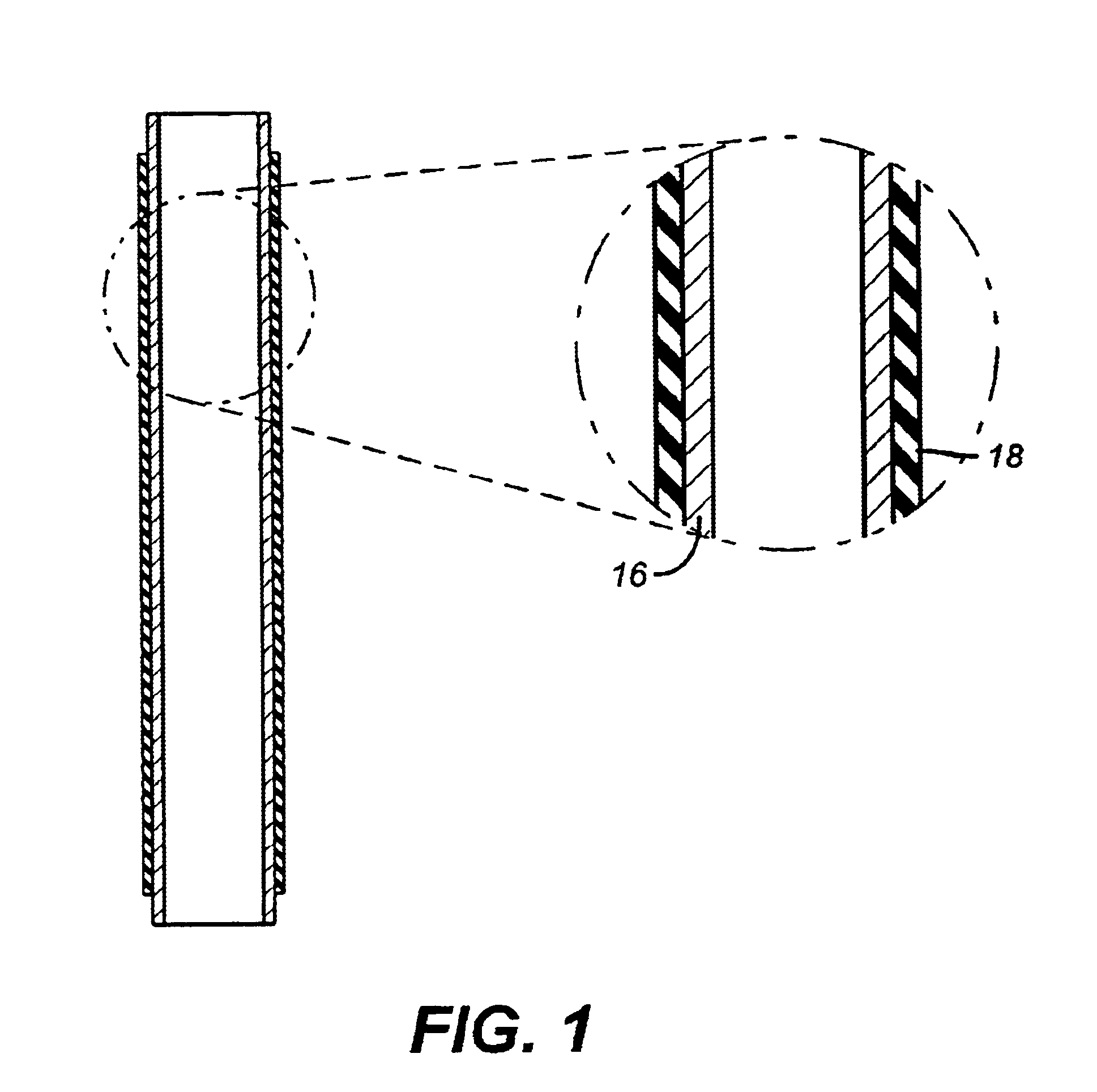
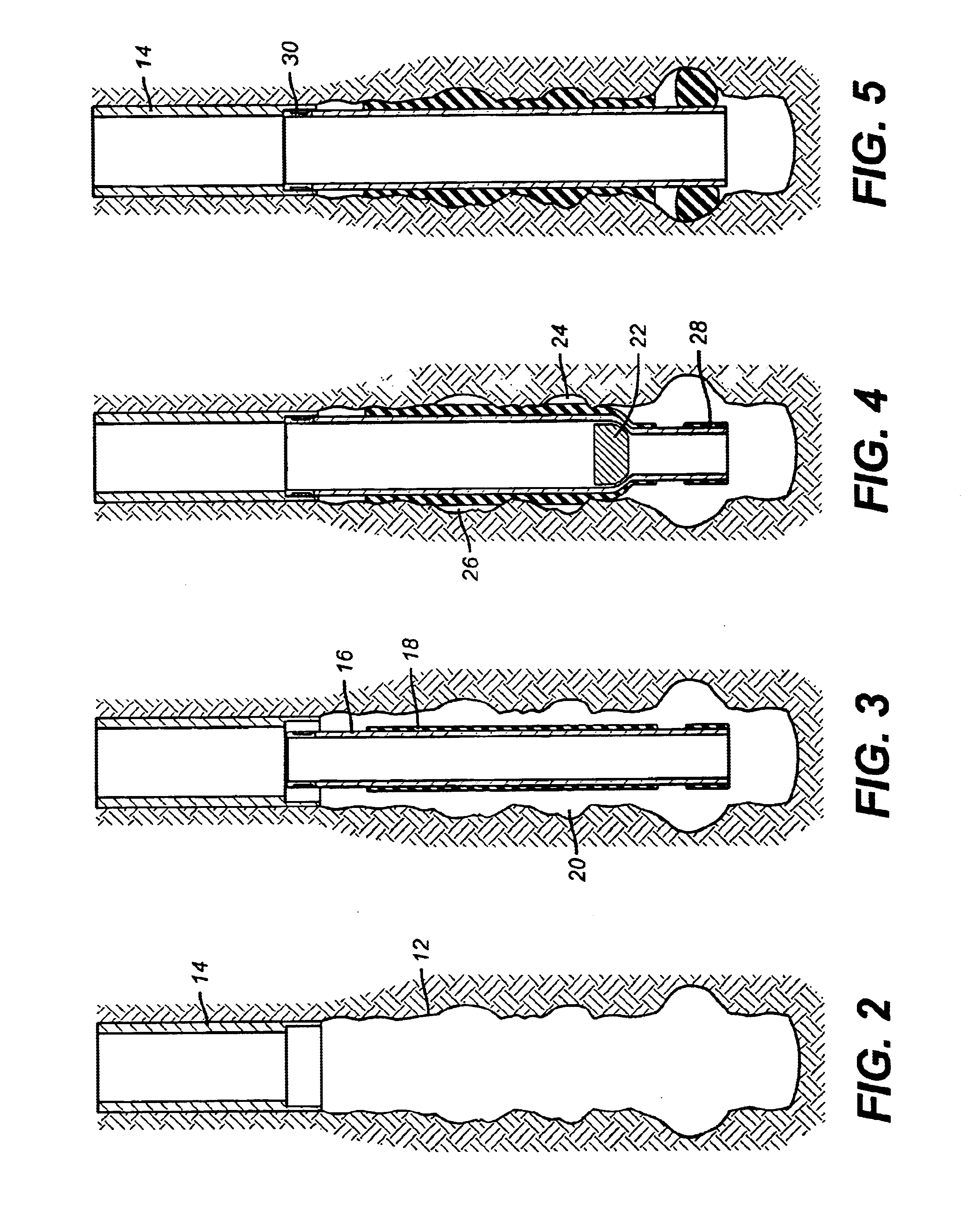
[0012]FIG. 1 shows a typical stand of casing or liner 16 in a much longer string that is to be inserted at a desired wellbore location. The wellbore 12 that has already been cased with casing 14 is shown in FIG. 2. FIG. 3 shows the stand of casing or liner 16 inserted into the wellbore and overlapping with casing 14. Depending on the dimensions of the wellbore and the covering 18, the annular space 20 between string 16 and wellbore 12 could be sealed by swelling of covering 18 without physical expansion of the string 16. Optionally, as shown in FIG. 4, a swage, schematically illustrated as 22 can expand the string 16 before the covering has finished swelling and while voids such as 24 and 26 still exist. When the expansion is complete and the swelling stops, FIG. 5 is the way the assembly will look. The string 16 is supported from casing 14 and fully expanded to approximately the same diameter. Alternatively or additionally, a packer or some other annular blocking device 28 can be p...


PUM


Abstract

A method of sealing casing or liners in a wellbore is described. The stands of casing or liner receive a jacket bonded to the outer surface. Preferably, the jacket is a rubber compound bonded to the outer wall. The formulation responds to well fluids to swell at a predetermined rate. The casing or liner can also be expanded with a swage preferably prior to the onset of significant jacket swelling. Packers and sealing hangers can be optionally added at the extremes of the casing or liner string to further secure against channeling between adjacent formations.

Description

FIELD OF THE INVENTION[0002]The field of this invention is methods designed to seal casing or liner in a wellbore using techniques involving a sealing material that swells downhole.BACKGROUND OF THE INVENTION[0003]Traditionally casing and liners have been sealed in the wellbore with cement that is pumped down internally and later displaced out the bottom of the casing or liner and into the annular space between the casing or liner and the wellbore. This procedure is expensive and requires the use of specialized equipment and specially trained personnel. The process is time consuming and the equipment takes up significant space such that in offshore platforms careful logistics are required to make room for the equipment when the cementing job is required. There are also uncertainties as to the distribution of the cement causing concerns of channeling of fluids from one zone penetrated by the casing or liner to an adjacent zone.[0004]In the past, packers that seal tubing to casing usi...

Claims


Application Information

Patent Timeline
Patent Type & Authority Patents(United States)
IPC IPC(8): E21B33/14E21B43/10
CPCE21B33/14E21B43/103E21B33/12E21B33/127
Inventor RICHARD, BENNETT M.CARMODY, MICHAEL A.JABS, MATTHEW J.
Owner BAKER HUGHES OILFIELD OPERATIONS LLC
Why Eureka
Try Eureka