Screen and method having a partial screen wrap

a screen and partial technology, applied in the field of screens, can solve the problem and achieve the effect of reducing the inside diameter of the screen inside the screen

Inactive Publication Date: 2005-02-01
SCHLUMBERGER TECH CORP
View PDF20 Cites 115 Cited by
  • Summary
  • Abstract
  • Description
  • Claims
  • Application Information

AI Technical Summary

Benefits of technology

In general, according to one embodiment, the present invention provides a partial filter media used to advantage with side conduits (i.e., alternate fl

Problems solved by technology

Typically, however, mounting a device (e.g., control line, side conduit, other equipment) adjacent the screen or inside the scr

Method used


Image

  • Screen and method having a partial screen wrap
  • Screen and method having a partial screen wrap
  • Screen and method having a partial screen wrap

Examples


Embodiment Construction

In the following description of the present invention, numerous details are set forth to provide an understanding of the present invention. However, it will be understood by those skilled in the art that the present invention may be practiced without these details and that numerous variations or modifications from the described embodiments may be possible.

In this description, the terms “up” and “down”; “upward” and downward”; “upstream” and “downstream”; and other like terms indicating relative positions above or below a given point or element are used in this description to more clearly described some embodiments of the invention. However, when applied to apparatus and methods for use in wells that are deviated or horizontal, such terms may refer to a left to right, right to left, or other relationship as appropriate.

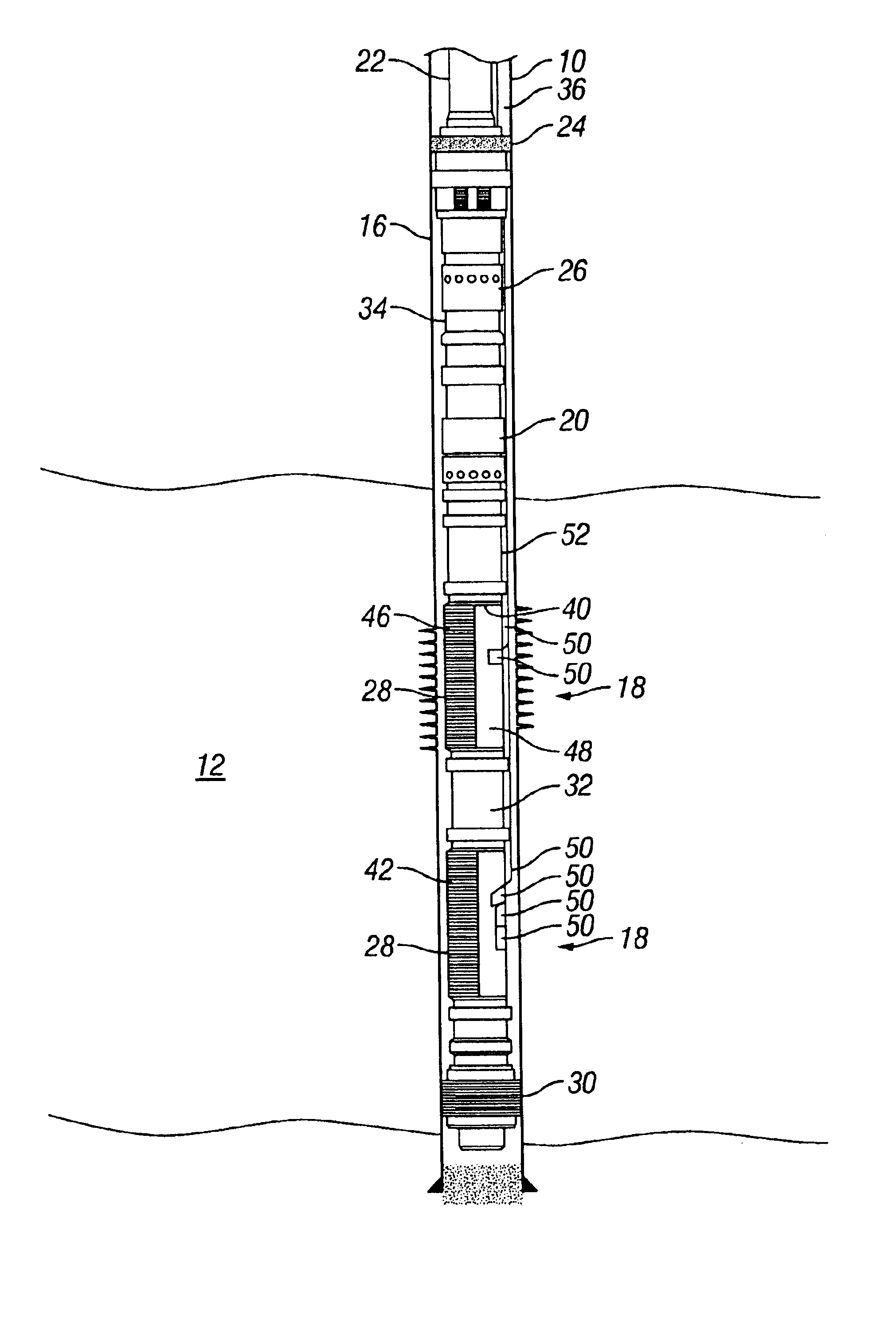
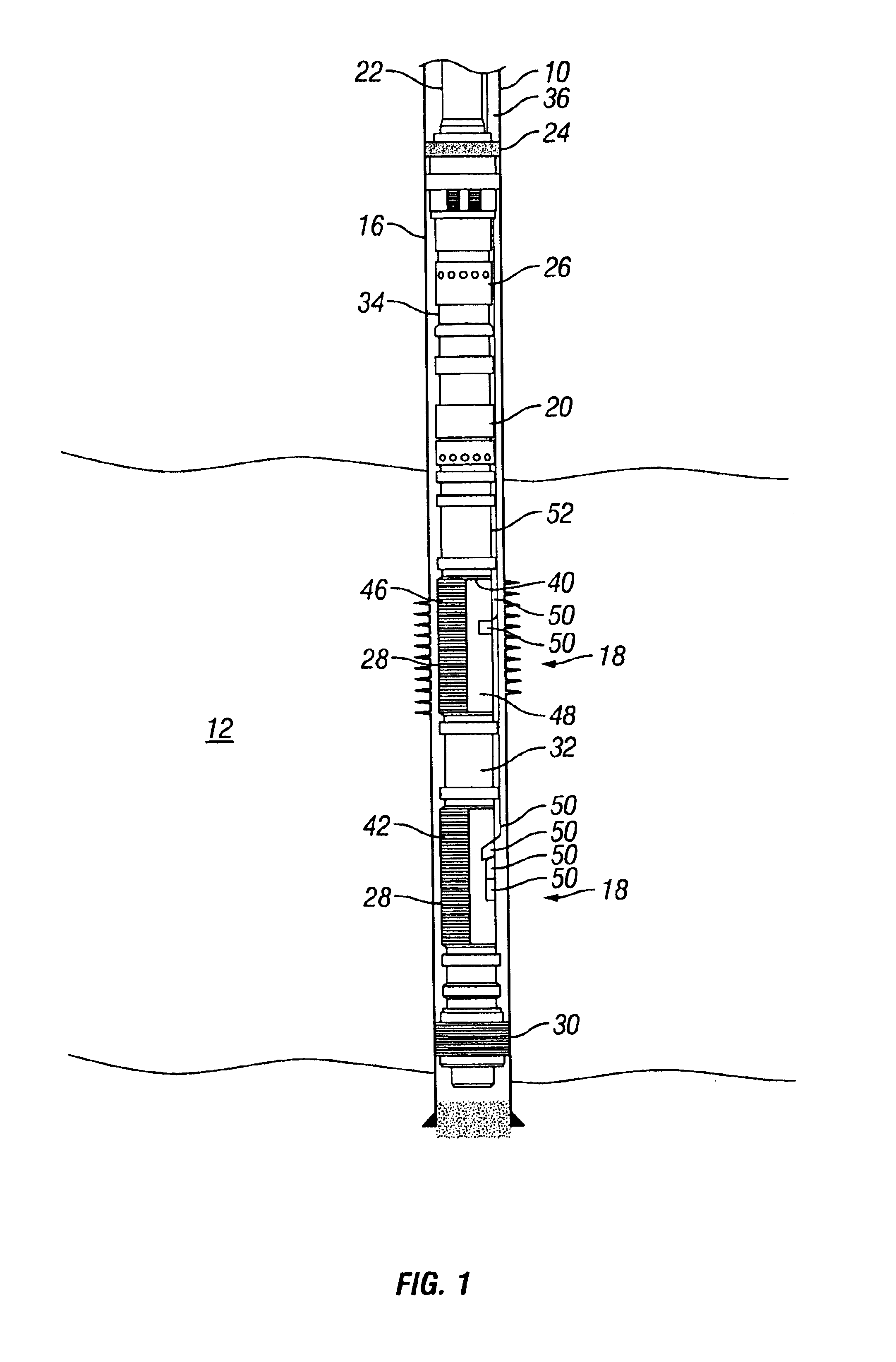
FIG. 1 illustrates a typical gravel pack completion in which a wellbore 10 penetrates a subterranean zone 12 that includes a productive formation. The wellbore 10 has ...


PUM


Abstract

The present invention provides a screen for a well that utilizes a partial screen wrapping used to advantage with side conduits (e.g., alternate flowpaths), control lines, intelligent completions devices, and the like. It is emphasized that this abstract is provided to comply with the rules requiring an abstract that will allow a searcher or other reader to quickly ascertain the subject matter of the technical disclosure. It is submitted with the understanding that it will not be used to interpret or limit the scope or meaning of the claims.

Description

FIELD OF THE INVENTIONThe present invention relates to a well screen for use in a wellbore aspects relates to a well screen. More specifically, the present invention relates to a partial filter media used to advantage with side conduits (i.e., alternate flowpaths), control lines, and the like.BACKGROUND OF THE INVENTIONIt is common to place a sand screen in a well to filter solids from the production fluid (e.g., hydrocarbons, water). It is often desirable to route cables or side conduits adjacent the screens. For example, a side conduit, or shunt tube, may be used to improve a gravel pack in a well. As another example, a control line may be routed to bypass at least a portion of the sand screen. Likewise, it may be desirable to route other types of conduits, like chemical injection lines, to bypass at least a portion of the screen. It may also be desirable to mount other equipment (e.g., sensors) adjacent the screens. Many other such examples exist.Typically, however, mounting a de...

Claims


Application Information

Patent Timeline
IPC IPC(8): E21B43/08E21B43/02E21B43/10A45C3/00E21B43/04
CPCE21B43/04E21B43/108E21B43/103E21B43/105E21B43/08A45C3/00
Inventor BIXENMAN, PATRICK W.JOHNSON, CRAIG D.DANOS, JAKE A.HACKWORTH, MATTHEW R.
Owner SCHLUMBERGER TECH CORP
Why Eureka
Try Eureka