Ink tank and ink jet printer

a technology of ink jet printer and ink tank, which is applied in printing and other directions, can solve the problems of inability to directly apply the detection system disclosed in the patent publication to the ink tank, and the amount of ink actually used

Inactive Publication Date: 2005-02-01
SEIKO EPSON CORP
View PDF17 Cites 82 Cited by
  • Summary
  • Abstract
  • Description
  • Claims
  • Application Information

AI Technical Summary

Benefits of technology

Accordingly, an object of the invention is to provide an ink tank which can eliminate such an unwanted situation that by the air b

Problems solved by technology

The ink end detecting method, which counts the amount of used ink and detects the ink end based on the count result, has the following problems.
An amount of used ink that is counted on the basis of those ink amounts may greatly deviate from the amount of ink actually used.
The result is that at a time point where the in

Method used


Image

  • Ink tank and ink jet printer
  • Ink tank and ink jet printer
  • Ink tank and ink jet printer

Examples


second embodiment

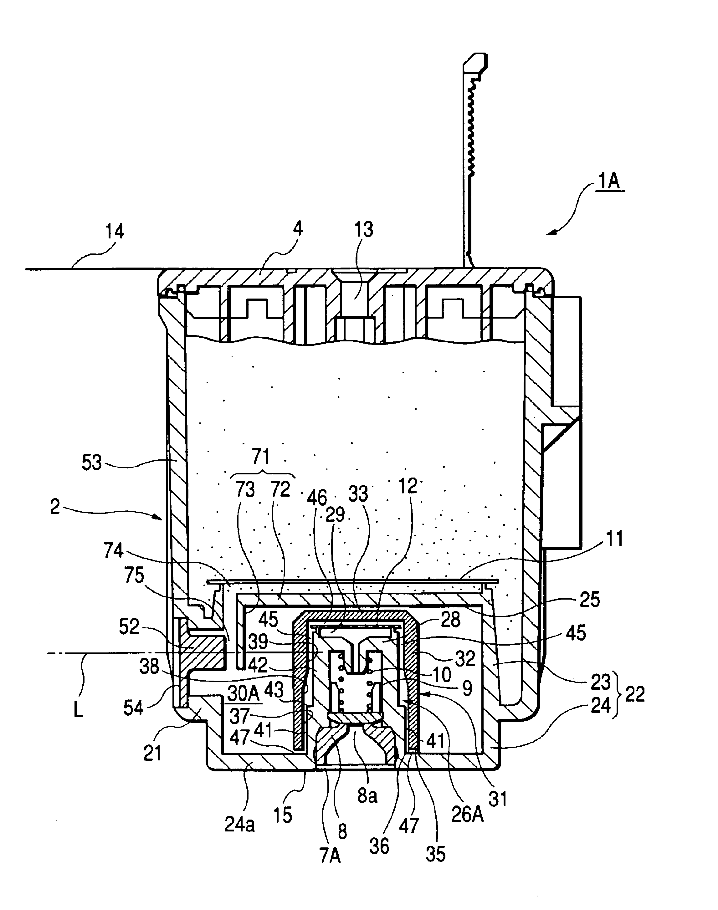
FIGS. 7 and 8 are cross sectional views showing major portions of an ink tank which is an second embodiment of the present invention. A basic construction of an ink tank 1A of the instant embodiment is substantially the same as of the ink tank 1 of the first embodiment except the construction including the sub ink chamber and the ink outlet. Accordingly, in FIGS. 7 and 8, like or equivalent portions will be designated by like reference numerals, and description will be given about only the different parts and portions. FIGS. 7 and 8 are cross sectional views taken on the same lines as those in FIGS. 5 and 6 showing the first embodiment. A structure of an ink passage which is formed between an ink outlet 7A and a main ink chamber 5 in the ink tank 1A will be described with reference to those figures. A cylindrical frame 22, rectangular in cross section, is provided in the bottom plate part 21 of the container body 2 in a state that it passes through the bottom plate part 21 and verti...

third embodiment

In the first and second embodiments, the partitioning part 61 (71) is formed integrally with the container body 2. The partitioning part may be a separated part, if required. In the third embodiment, a partitioning part 71 is formed integrally with a cup-like cap 31A of the second embodiment. This will be described with reference to FIGS. 12 through 14. A basic construction of an ink tank 1B of the instant embodiment is the same as each of the ink tanks 1 and 1A in the embodiments 1 and 2, except a partitioning member. In those figures, like or equivalent portions are designated by like reference numerals. Description will be given about only the different portions.

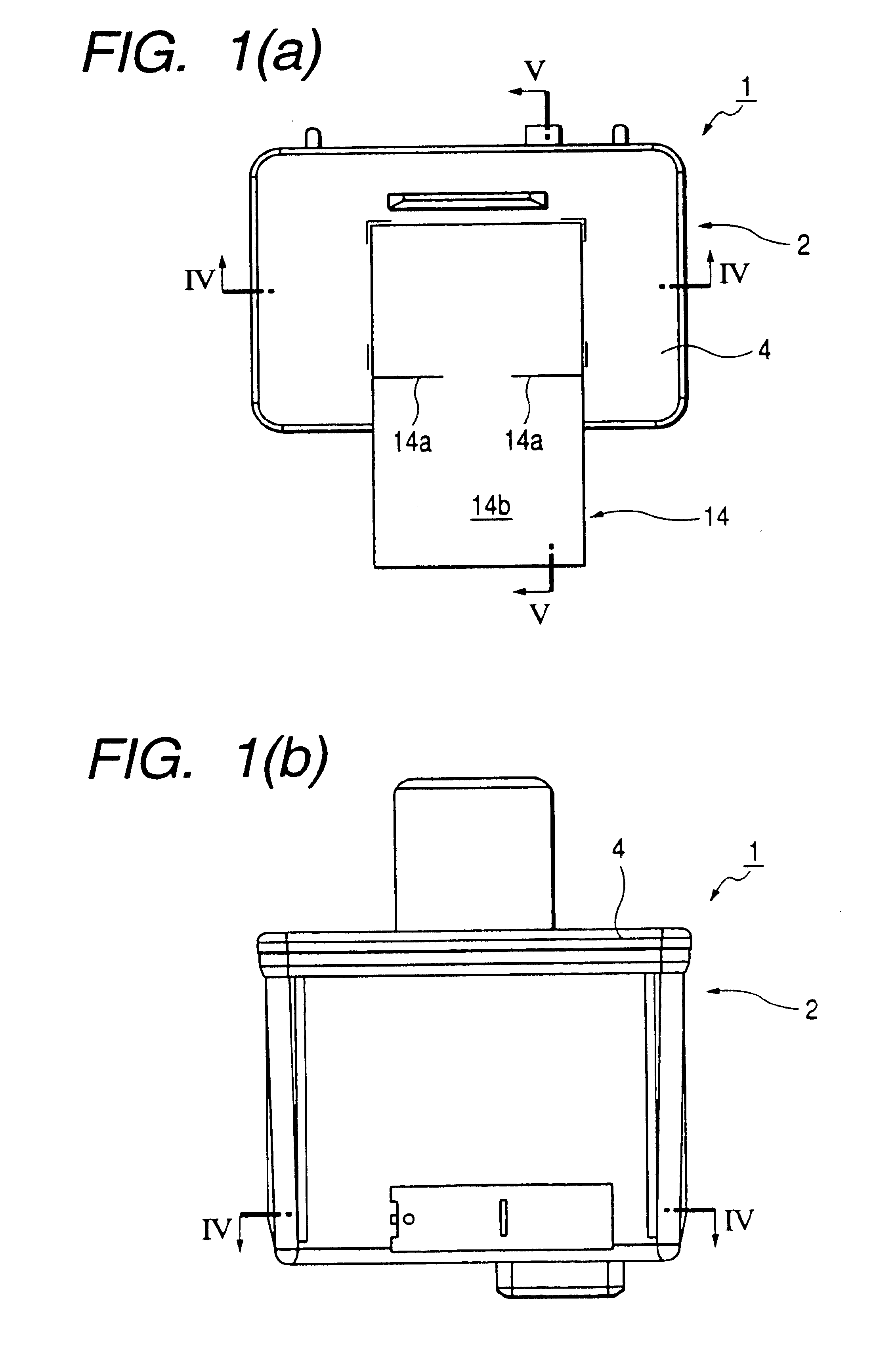
FIG. 12 is a view showing a partitioning member according to the third embodiment of the invention. FIG. 13(a) shows an ink tank according to the third embodiment of the invention, and is a partially enlarged, cross sectional view taken on line V—V in FIG. 1. FIG. 13(b) is a partially enlarged, longitudinal sectional view...


PUM


Abstract

An ink tank of the foam type which is provided with a detected portion capable of exactly and surely detecting the amount of ink used by the printer or remaining in the ink tank. The ink tank includes a sub ink chamber that is diposed or formed between a main ink chamber and an ink outlet of an ink tank of a foam type. When an amount of air flowing into the sub ink chamber increases, one or more reflecting surfaces of a right-angled prism, which function as ink interfaces, resume their original function of reflecting surfaces, thereby enabling the detection of an ink end. Air bubbles having entered the sub ink chamber are surely led onto the one or more reflecting surfaces by a bubble storage part. At an ink passage having a narrow width, which is defined by the one or more reflecting surfaces, air bubbles are pressed against the one or more reflecting surfaces to be put to a crushed state and in surface contact with the latter. Air bubbles are surely led onto the one or more reflecting surfaces, and are crushed and pressed against the reflecting surfaces. This configuration prevents the one or more reflecting surfaces from being covered with ink retained in spaces among the air bubbles. Therefore, the ink end can be detected surely and exactly.

Description

BACKGROUND OF THE INVENTION1. Technical FieldThe present invention relates to an ink tank with an ink absorbing member absorptively retaining ink, and more particularly to an ink tank with a detected portion capable of exactly detecting when ink in the ink tank has been depleted, including the amount of ink used or remaining in the ink tank, and an ink jet printer using the ink tank as an ink supplying source.2. Related ArtAn ink tank of a foam type is known for the ink tank of an ink jet printer. The foam type ink tank is composed of a foam containing part containing a foam absorptively retaining ink, an ink outlet communicating with the foam containing part, and an air communication port through which the foam containing part is opened to the air. When ink is sucked through the ink outlet in response to an ejection pressure of the ink jet head, an amount of air corresponding to an amount of sucked ink flows from the air communication port to the foam containing part.In the case of...

Claims


Application Information

Patent Timeline
IPC IPC(8): B41J2/175
CPCB41J2/17513B41J2/17523B41J2/17566B41J2/19B41J2/17553B41J2002/17573B41J2/195
Inventor NISHIOKA, ATSUSHIHANAOKA, YUKIHIROYAMADA, MANABU
Owner SEIKO EPSON CORP
Why Eureka
Try Eureka