Polygonal fuel cell apparatus and method of making

a fuel cell and polygonal technology, applied in the field of polygonal cross-section fuel cells, can solve problems such as difficulty in sealing against gas leakag

Inactive Publication Date: 2005-02-01
GENERAL ELECTRIC CO
View PDF6 Cites 20 Cited by
  • Summary
  • Abstract
  • Description
  • Claims
  • Application Information

AI Technical Summary

Problems solved by technology

The flat plate design has an advantage of high power density but su

Method used


Image

  • Polygonal fuel cell apparatus and method of making
  • Polygonal fuel cell apparatus and method of making
  • Polygonal fuel cell apparatus and method of making

Examples


Embodiment Construction

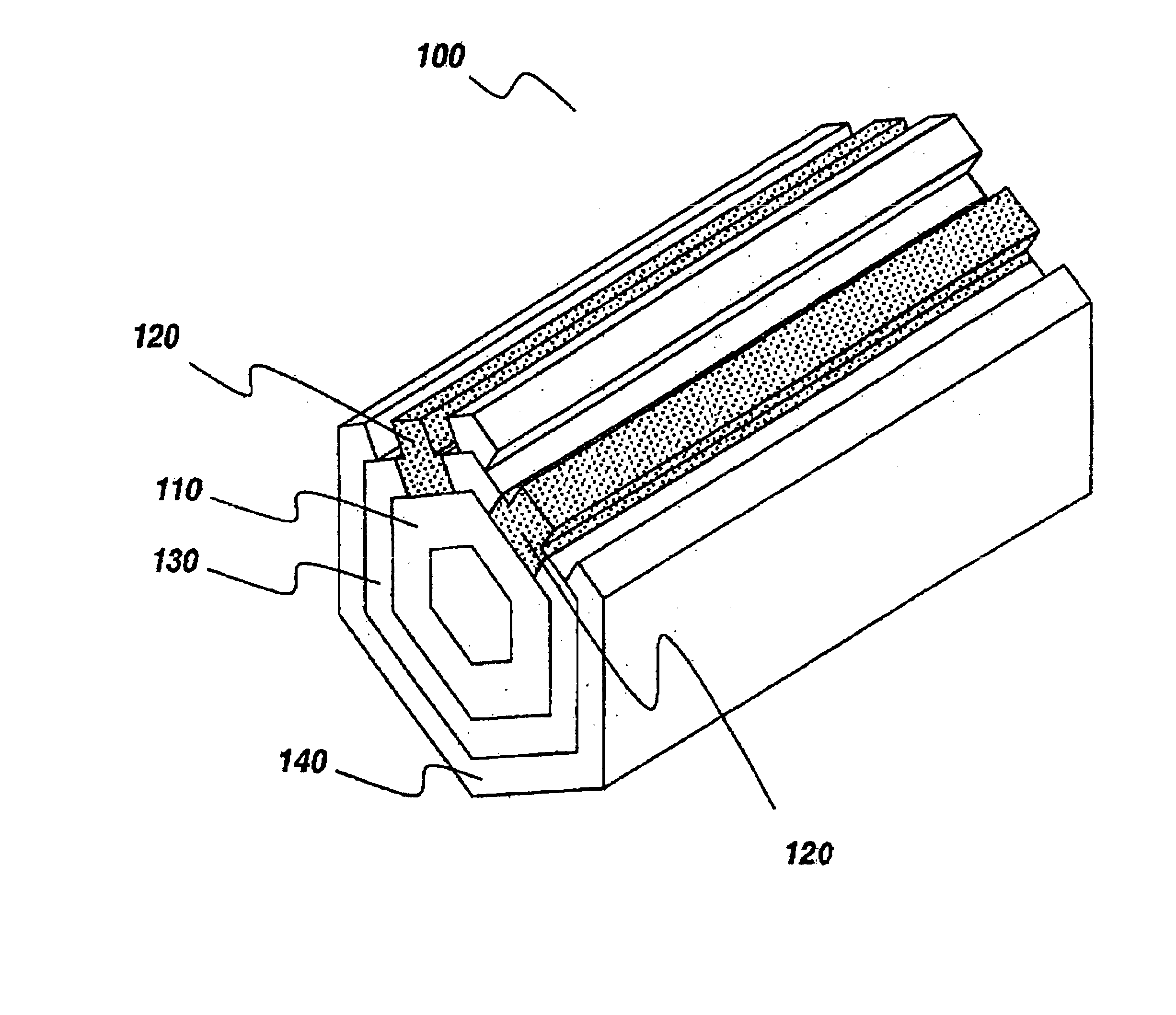
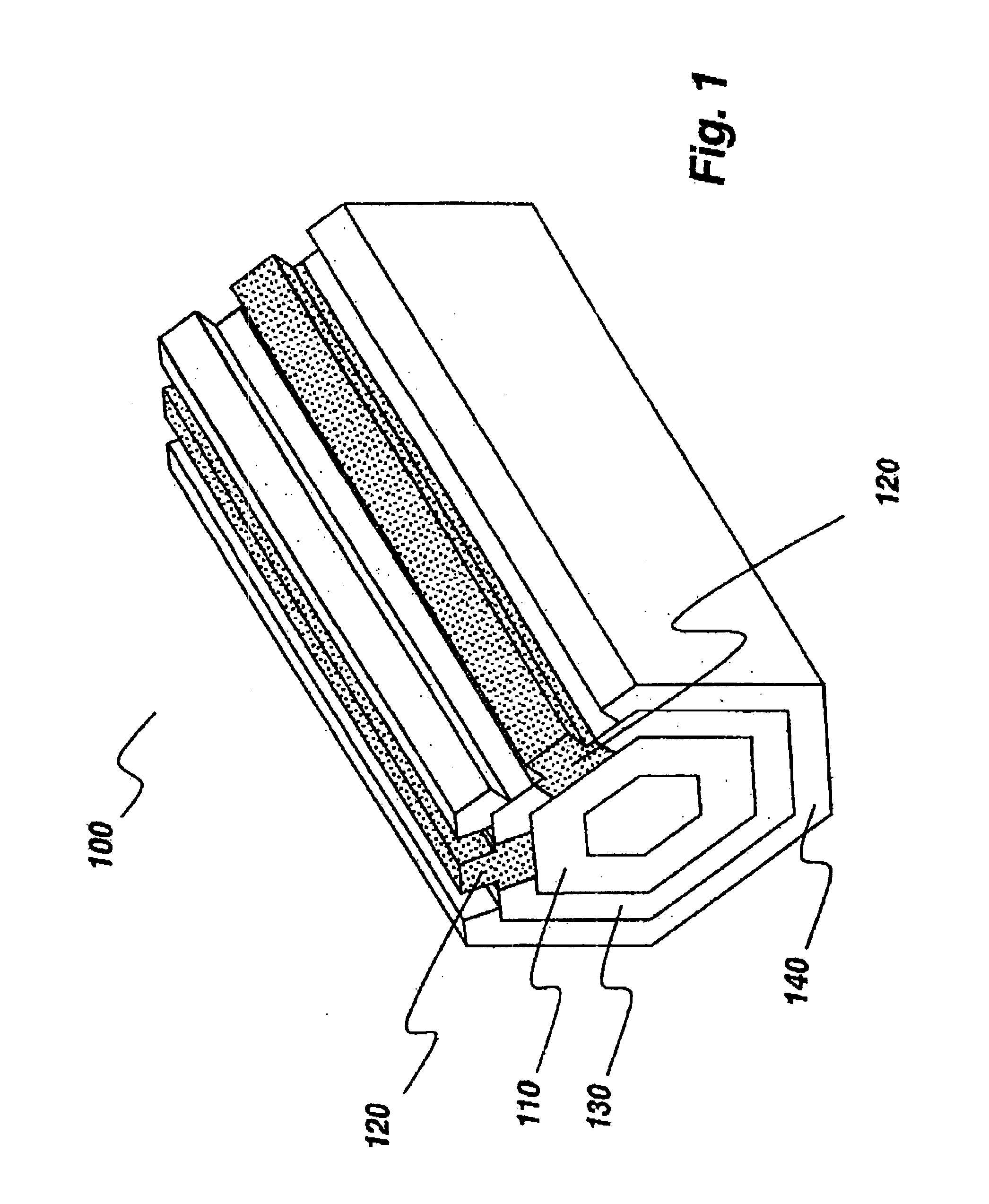
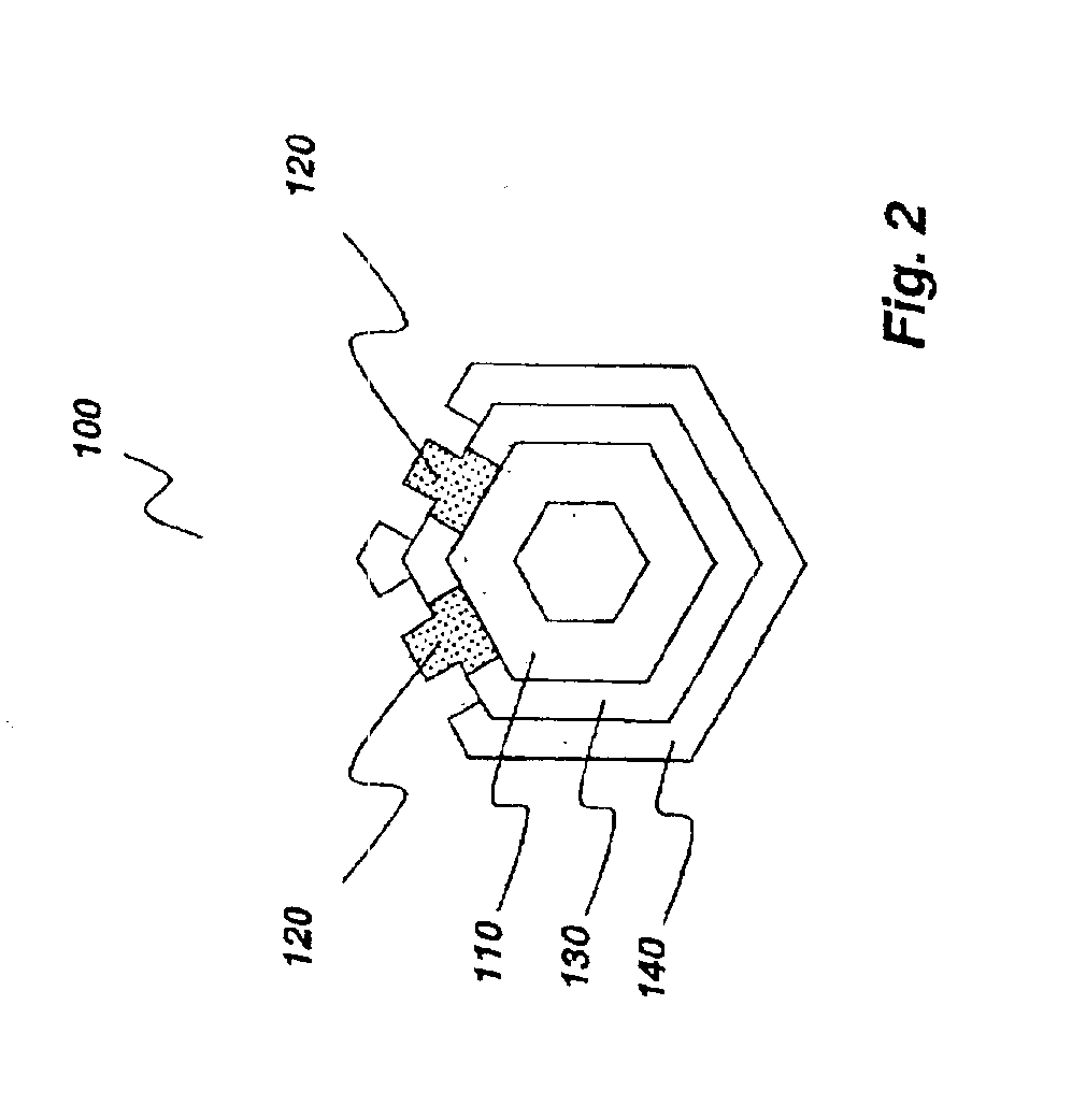
In accordance with one embodiment of the present invention, FIG. 1 illustrates an isometric projection of a polygonal fuel cell 100 comprising a cathode layer 110, a contact layer 120, and an anode layer 140. Cathode layer 110 has a tubular shape through which an oxidant gas flows in operation. Contact layer 120 is electrically coupled to cathode layer 110 to provide an external electrical contact and is disposed to leave an uncovered cathode surface portion. Electrolyte layer 130, disposed on the uncovered cathode surface portion, and anode layer 140, electrically isolated from contact layer 120 and disposed on electrolyte layer 130, complete polygonal fuel cell 100. In operation, fuel gas flows over anode layer 140.

Anode layer 140 is disposed on electrolyte layer 130 such that polygonal fuel cell 100 has a polygonal cross section. Compared to a circular tubular design, the tubular shape of cathode layer 110 provides comparable gas sealing capability, while the polygonal cross sect...


PUM


Abstract

In one embodiment of the present invention, a polygonal fuel cell comprises: a cathode layer having a tubular shape; a contact layer electrically coupled to and disposed on the cathode layer to leave an uncovered cathode surface portion; an electrolyte layer disposed on the uncovered cathode surface portion; and an anode layer electrically isolated from the contact layer, disposed on the electrolyte layer such that the polygonal fuel cell has a polygonal cross section to facilitate dense packing.

Description

BACKGROUND OF INVENTIONThe present invention relates generally to the field of fuel cells and more specifically to fuel cells with polygonal cross-sections.In a wide variety of applications, fuel cells are used to provide relatively cleaner and higher efficiency electrical power compared to fossil fuel burning electrical power plants.Two design geometries have come to dominate the fuel cell field: the flat plate design and the circular tubular design (see, for example, Fuel Cell Handbook (Fifth Edition), Chapter 8, EG&G Services, available from National Technical Information Service, U.S. Department of Commerce, Springfield, Va.). The flat plate design has an advantage of high power density but suffers a disadvantage of being difficult to seal against gas leakage. Conversely, the circular tubular design offers the benefit of a more reliable gas seal, but at the cost of a reduced power density. An opportunity exists, therefore, to design a new fuel cell geometry which will retain the...

Claims


Application Information

Patent Timeline
IPC IPC(8): H01M8/12H01M8/24
CPCH01M8/1213H01M8/243Y02E60/525Y02E60/521H01M8/241H01M8/2404Y02E60/50Y02P70/50
Inventor VORA, NISHITH PRAMODBUNKER, RONALD SCOTTHALE, LESTER RUSSELLGOODMAN, GEORGE CHARLESDEY, DEBASHIS
Owner GENERAL ELECTRIC CO
Why Eureka
Try Eureka