Trigger operated electronic device

a technology of electronic devices and triggers, which is applied in the direction of cathode-ray tube indicators, instruments, indoor games, etc., can solve the problems of inconvenient operation, difficulty, and relatively clumsy computer system of the mouse,

Inactive Publication Date: 2005-02-01
SMK LINK ELECTRONICS
View PDF21 Cites 611 Cited by
  • Summary
  • Abstract
  • Description
  • Claims
  • Application Information

AI Technical Summary

Benefits of technology

By this invention, there is provided a system which minimizes the disadvantages of the prior devices and systems.

Problems solved by technology

This mouse is a relatively clumsy system for computer operation.
What is particularly unwieldy is the fact that the hand of an operator needs to be moved to the location of the mouse on a mouse pad or base.
This is particularly inconvenient because the operator's hands also need to be available for use to operate a computer keyboard or for use for other purposes unassociated with the computer.
This difficulty is further compounded by the fact that the mouse pad is usually located in a removed position relative to the other computer components.
One therefore finds that operating a computer with a mouse in this hard wired fashion, while one is doing extra work, is relatively awkward.

Method used


Image

  • Trigger operated electronic device
  • Trigger operated electronic device
  • Trigger operated electronic device

Examples


example 2

Southwesterly Direction

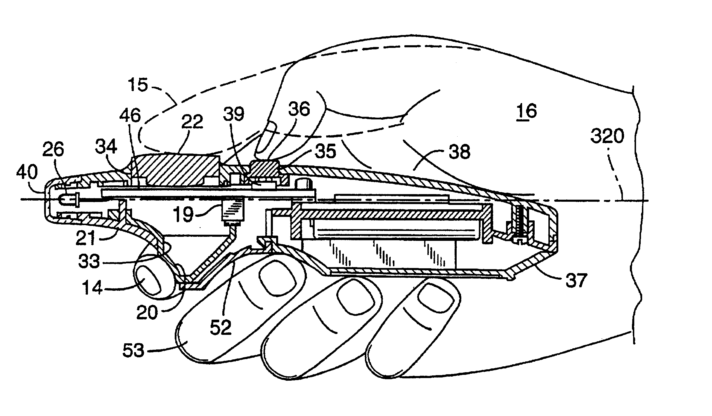
For the user to move the cursor 49 in a southwesterly direction, the user would naturally pull the thumb 15 back. For a right-handed mouse user, this would push the thumb away from the palm 16. This motion would cause the trace 41 to contact the trace 43, which moves the cursor 49 to the left, and also cause the trace 44 to contact the trace 42. This moves the cursor 49 down. As with example 1, the harder the user presses in that direction, the larger the contact area between the traces 47 and the conductive plate 46, making the cursor 49 move faster.

Any other movement is a similar motion to the above two examples.

The electronic circuit 17 operates as follows:

As the user applies pressure to one or more of the four quadrants underneath the second switch button 22, the conductive plate 46 for that quadrant becomes connected to the common portion of the plate 46. As more pressure is applied, the resistance decreases, since there is more current carrying area when...


PUM


Abstract

A device particularly for use with a computer comprises a housing for location at least partly between two fingers of a user's hand and an electronic circuit mounted on a board within the housing. The circuit includes a switch responsive to pressure selectively to open and close an electronic circuit, and conductive elements arranged on the board mounting the electronic circuit. A first control element is mounted with the housing and responsive to finger pressure such that pressure applied to the first control element causes the element to operate the switch. The first control element is movable with respect to a hinge such that finger action acts to cause the control element to swivel as a trigger about the hinge and thereby interact with the switch. The second control element includes a flexible material mounted such that pressure applied to the flexible material in different directions and positions acts to change the electrical relationship between the conductive elements on the board and thereby vary an output signal from the electronic circuit. The rear portion of the housing includes a receptacle for receiving removable battery means for powering the electronic circuit. There is an infra-red output signal transmitted to a receiver for operating the computer. The first control element is located substantially below the second control element, and the first control element being in a bottom face of the housing.

Description

BACKGROUNDHaving an ergonomically effective mouse for operating a computer is highly desirable.This invention relates to a trigger operated electronic device. In particular, it concerns a mouse for operating a cursor in a computer system.A conventional mouse for operating a computer system is one which is hard wired to the computer and which physically moves over a base. The mouse movement is effected by having a hand grasp the top of the unit and moving the mouse on the base. Below the top of the unit there is a ball mounted in a track and as the ball rotates, the mouse moves on the base. There are usually at least two switches on the top face of the mouse. Pressing one or more switches in an appropriate sequence and for appropriate times causes an electrical signal to be transmitted from the mouse to the computer, which is then operated. Conventionally, the shape of the mouse is one which fits under the palm of the hand when the palm of the hand is turned to face downwardly.This m...

Claims


Application Information

Patent Timeline
Patent Type & Authority Patents(United States)
IPC IPC(8): G06F3/033H01H9/02H01H25/04A63F13/219
CPCG06F3/0338H01H9/0214H01H2009/0257H01H25/041H01H9/0235
Inventor TICKLE, JAMES DEXTER
Owner SMK LINK ELECTRONICS
Why Eureka
Try Eureka