
Transmission power level estimation

Inactive Publication Date: 2005-02-01
INTERDIGITAL TECH CORP
View PDF9 Cites 36 Cited by
  • Summary
  • Abstract
  • Description
  • Claims
  • Application Information

AI Technical Summary

Benefits of technology

The invention generally relates to wireless communication systems. In particular, the invention relates to estimating transmission power levels in such systems.

Problems solved by technology

Since multiple communications are simultaneously carried over the same frequency spectrum, one user's communications may interfere with another user's.
When a new user or user service is added to a system, the new user will create interference to existing users communicating at the same time.
However, some transmitters may be near their transmission power limits.
As a result, adding the new user may create an unacceptable quality of service (QOS) for existing users.
If a user's transmission power level is unacceptable, such as by being over its transmission power level capabilities, the new user is not admitted.

Method used


Image

  • Transmission power level estimation
  • Transmission power level estimation
  • Transmission power level estimation

Examples


Embodiment Construction

FIG. 3 is a simplified RNC 28 for use in transmission power level estimation. The RNC 28 has a RRM device 36 and a measurement collection device 38. The measurement collection device 38 collects various measurements from other components of the network, such as the node-Bs 24 and the UEs 22. These measurements include transmission power levels (both uplink and downlink), pathloss information and other information. The RRM device 36 uses the measurements in determining efficient assignment of resources which is sent to the other components. The RRM device has a transmission power level estimation block 37 for use in determining the estimated transmission power levels.

FIG. 4 is a simplified node-B 24 for use in transmission power level estimation. An antenna 40 receives radio frequency signals over a radio channel from the UEs 22. The received signals are passed through an isolator or switch 42 to a receiver 46 and a measurement device 48. A channel assignment device 44, which receive...


PUM


Abstract

A model for noise rise of users in relation to an interference measure, a pathloss and a desired signal to interference ratio is provided. For a selected user, a pathloss, an interference measure and a desired signal to interference ratio is determined. A noise rise for the selected user is determined using the determined interference measure, pathloss, desired signal to interference ratio and the noise rise model. The selected user transmission power level is estimated using the determined noise rise.

Description

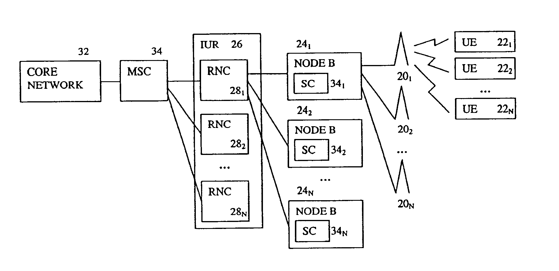
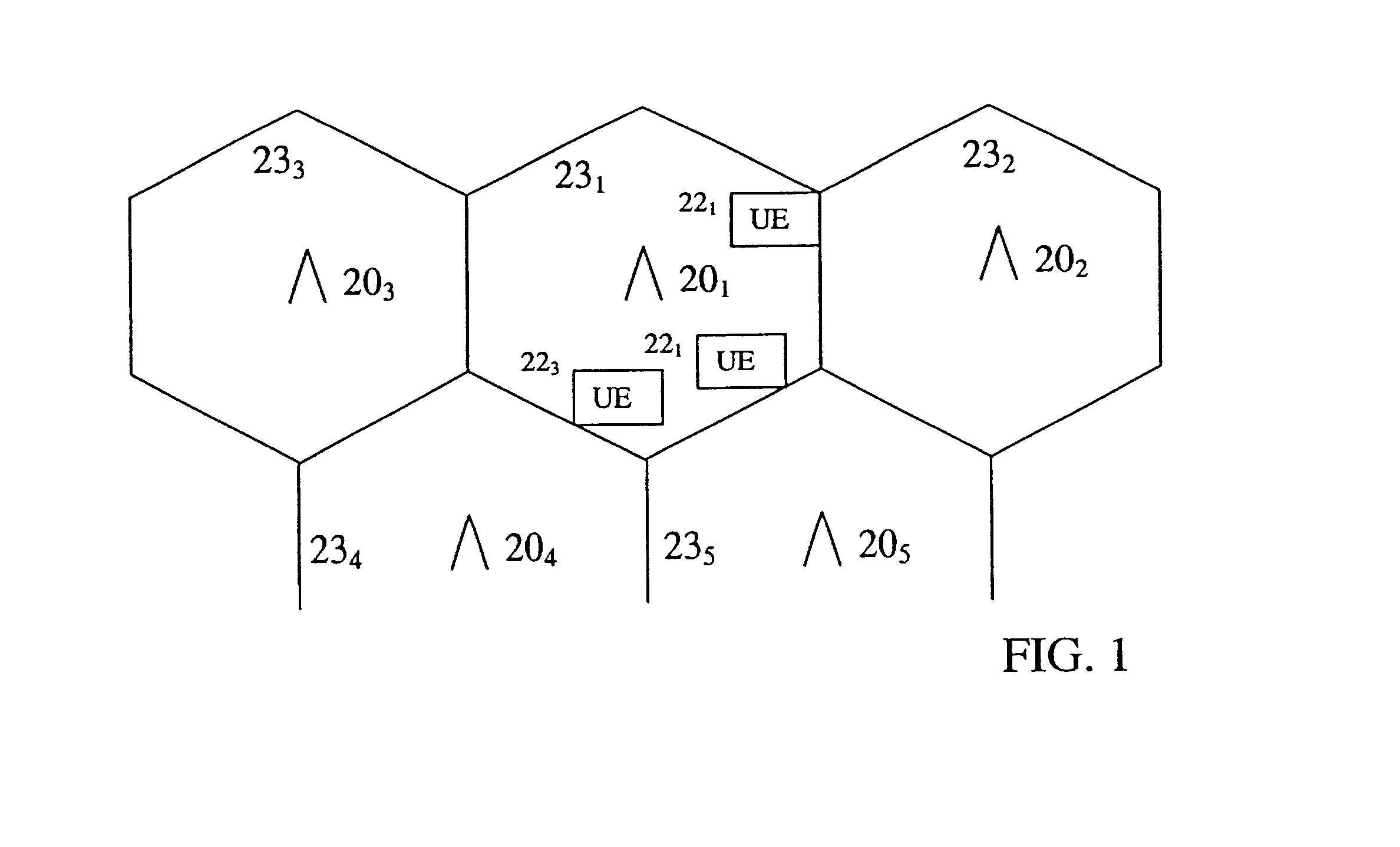
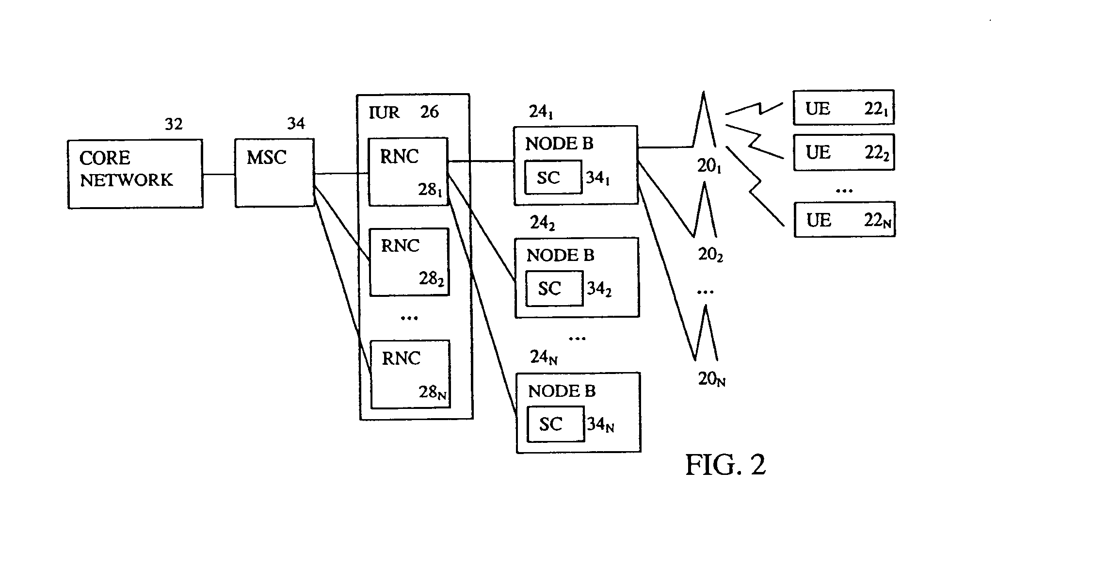
BACKGROUNDThe invention generally relates to wireless communication systems. In particular, the invention relates to estimating transmission power levels in such systems.FIG. 1 depicts a physical layout of a wireless communication system. The system has a plurality of base stations 20. Each base station 20 communicates with user equipments (UEs) 22 in its operating area or cell 23. Communications transmitted from the base stations 20 to the UEs 22 are referred to as downlink communications and communications transmitted from the UEs 22 to the base stations 20 are referred to as uplink communications.A network perspective of a wireless communication system is shown in FIG. 2. Each node-B 24 within the system communicates with associated UEs 22 or users. Each node-B 24 has a single site controller (SC) 34 associated with either a single or multiple base stations 20. A group of node-Bs 24 is connected to a radio network controller (RNC) 281. To transfer communications between RNCs 28, ...

Claims


Application Information

Patent Timeline
IPC IPC(8): H04B7/005H04B17/00H04Q7/38H04B1/04H04B7/26H04J13/00H04W28/16H04W52/16H04W52/22H04W52/24H04W52/34H04W52/50
CPCH04W28/16H04B17/382H04W52/226H04W52/228H04W52/241H04W52/242H04W52/243H04W52/50H04B17/309H04B17/373H04W52/246H04W52/34H04B17/327H04B17/345H04W52/16H04B7/2603H04B17/336H04W52/146H04W52/22H04W52/245H04W28/04
Inventor ZEIRA, ELDADZHANG, GUODONG
Owner INTERDIGITAL TECH CORP
Features
  • Generate Ideas
  • Intellectual Property
  • Life Sciences
  • Materials
  • Tech Scout
  • Unparalleled Data Quality
  • Higher Quality Content
  • 60% Fewer Hallucinations
Learn More