Packet buffer device and packet switching device

a packet buffer and packet switching technology, applied in data switching details, data switching networks, time-division multiplexing selection, etc., to achieve the effect of adequate processing and reliable maintaining the entire consistency

Inactive Publication Date: 2005-02-01
KK TOSHIBA
View PDF12 Cites 6 Cited by
  • Summary
  • Abstract
  • Description
  • Claims
  • Application Information

AI Technical Summary

Benefits of technology

It is therefore an object of the invention to provide a packet buffer device capable of reliably maintaining the entire consistency even when the leaf queue of a copy destination is deleted from a coupled packet queue. That is, it is the object of the invention to provide a packet buffer device ensuring adequate processing even upon a change in condition of a packet queue. It is a further object of the invention to provide a packet switching device using such a packet buffer device.

Problems solved by technology

First referring to FIG. 10, in the case where no packets have ever been accumulated in the next leaf queue LQ(n+1) upon deleting the leaf queue LQ(n), the header pointer of the leaf queue LQ(n+1) is still indefinite, and packets of the leaf queue LQ(n) cannot be changed to the leaf queue LQ(n+1).

Method used


Image

  • Packet buffer device and packet switching device
  • Packet buffer device and packet switching device
  • Packet buffer device and packet switching device

Examples


Embodiment Construction

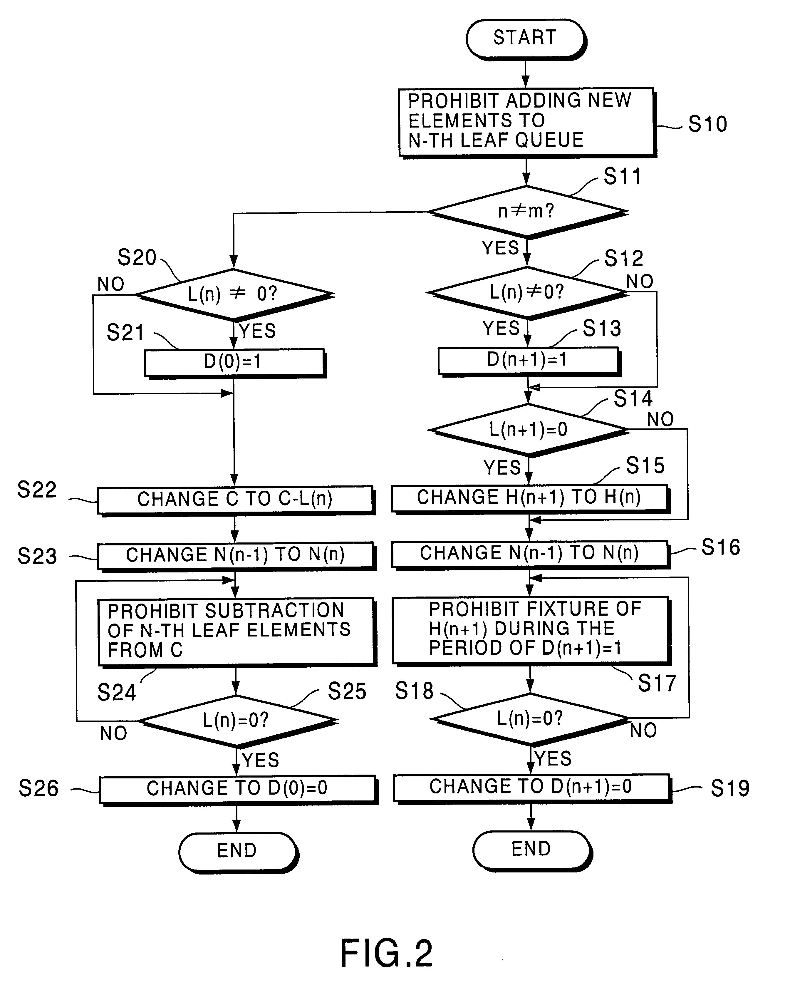
The packet buffer device according to an embodiment of the invention has its feature in providing each leaf table and each root table of a coupling management table for managing a coupled packet queue with a delete operation identifier indicating that a preceding leaf queue is under delete operation, and thereby ensuring consistency of the coupled packet queues and the coupling management table after deletion of the leaf queue. It is explained below in greater detail.

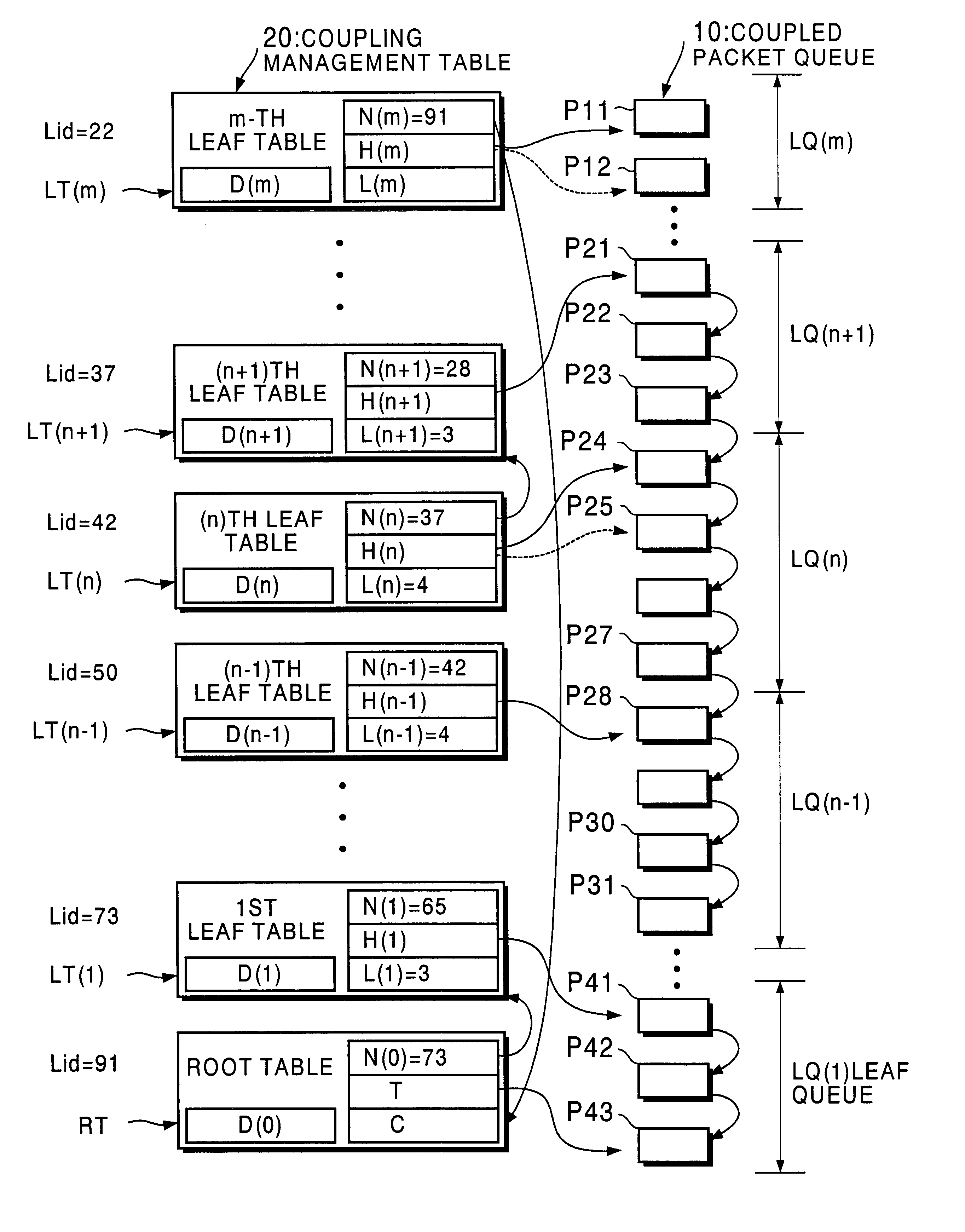
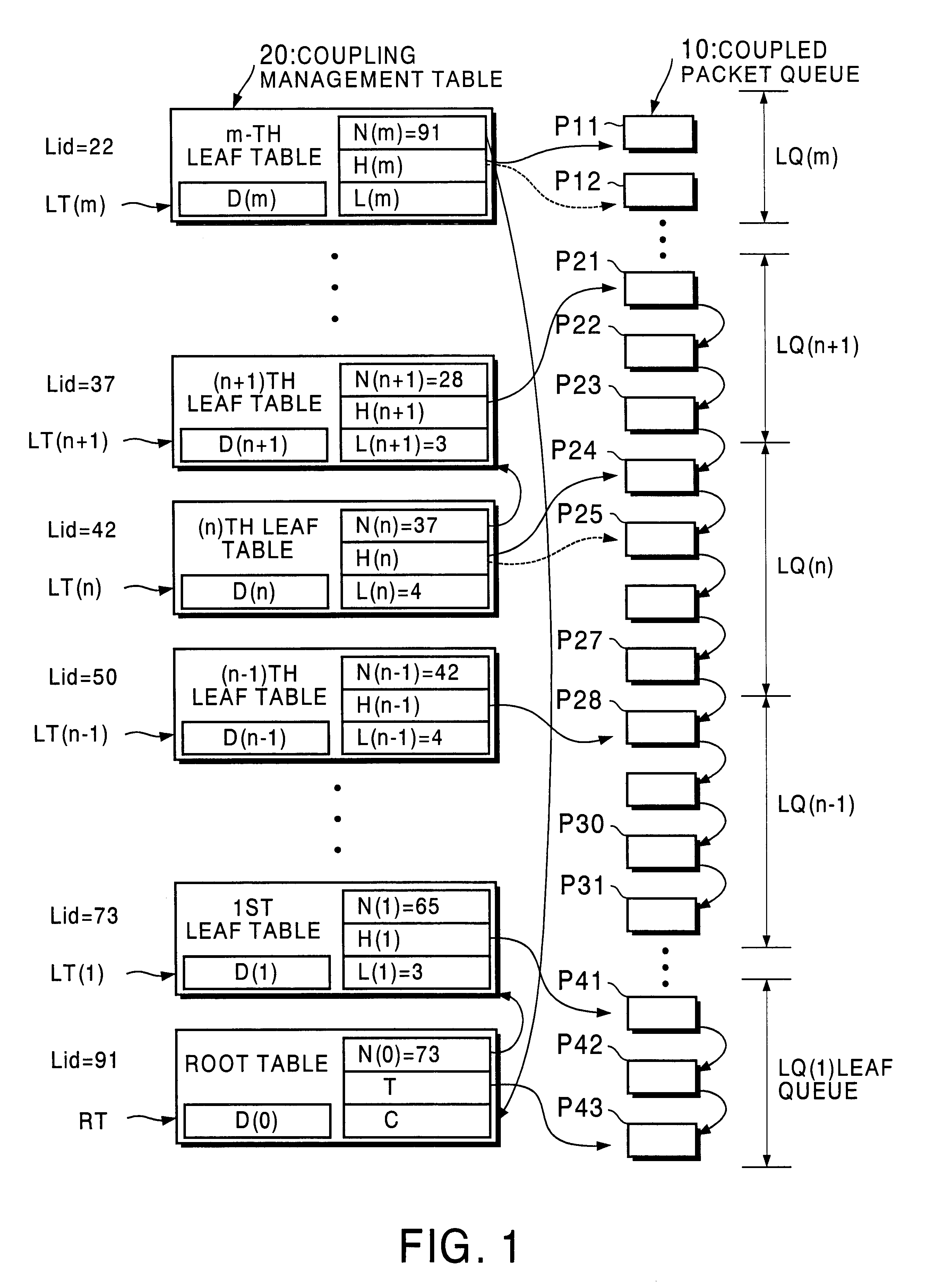
FIG. 1 is a block diagram that shows configuration of a coupled packet queue 10 and a coupling management table 20 for managing the entirety of the coupled packet queue 10 in a packet buffer device according to an embodiment of the invention.

In the example shown in FIG. 1, the coupled packet queue 10 of a certain flow is composed of m leaf queues LQ(1) through LQ(m). That is, in this example, multi-casting made up of m copy destinations is formed. In this embodiment, the leaf queues LQ(1) through LQ(m) do not store pack...


PUM


Abstract

In respective leaf tables (LT(1) to LT(m)) of a coupling management table (20), there are provided delete operation identifiers (D(1) to D(m)) indicating that leaf queues (LQ) respectively next to them toward the upstream direction are under delete operation. When one of the leaf queues (LQ(n)) should be deleted, if the leaf queue (LQ(n)) to be deleted stores any element, the delete operation identifier (D(n+1)) is set to 1. Thereby, the leaf table (LT(n−1)) can acknowledge that the leaf queue (LQ(n)) is currently under delete operation. Therefore, the coupled packet queue after deletion of the leaf queue and the coupling management table can be maintained consistent.

Description

CROSS REFERENCE TO RELATED APPLICATIONThis application claims benefit of priority under 35 U.S.C. § 119 to Japanese Patent Application No. H11-369431, filed on Dec. 27, 1999, the entire contents of which are incorporated by reference herein.BACKGROUND OF THE INVENTION1. Field of the InventionThis invention relates to a packet buffer device and a packet switching device that once store and then transfer input packets, and more particularly, to a packet buffer device and a packet switching device for realizing the function of delivering packets to a plurality of destinations.2. Description of the Related Background ArtJapanese Patent Laid-Open Publication No. H 10-145387 discloses a packet buffer device in which the queue access throughput does not depend on the number of destinations. FIG. 8 is a block diagram showing a part of the interior structure of a packet switching device using a packet buffer device disclosed in that publication.As shown in FIG. 8, formed inside the packet bu...

Claims


Application Information

Patent Timeline
Patent Type & Authority Patents(United States)
IPC IPC(8): H04L12/56H04Q11/04H04L12/18H04L49/9015
CPCH04L49/30H04Q11/0478H04L49/3081H04L49/3018H04L49/3027H04L49/351H04L2012/5681
Inventor HASEGAWA, JUNSAITO, TOSHITADASHIMOJO, YOSHIMITSU
Owner KK TOSHIBA
Why Eureka
Try Eureka