
Display device with built-in touch sensor, and drive method for same

Inactive Publication Date: 2021-05-06
SHARP KK
View PDF0 Cites 1 Cited by
  • Summary
  • Abstract
  • Description
  • Claims
  • Application Information

AI Technical Summary

Benefits of technology

The patent describes a touch display device that can detect touch using a stylus pen or other operation means. The device has multiple sensor electrodes arranged in two directions, which allows for accurate touch detection. This configuration allows for efficient use of analog front ends, resulting in a small-scale circuit that can detect touch accurately even when not using a finger.

Problems solved by technology

However, the out-cell type touch panel has had problems of an increase in weight and thickness of the entire device including the display panel and the touch panel and an increase in power required for driving the touch panel.

Method used


Image

  • Display device with built-in touch sensor, and drive method for same
  • Display device with built-in touch sensor, and drive method for same
  • Display device with built-in touch sensor, and drive method for same

Examples


Embodiment Construction

[0063]Hereinafter, an embodiment of the present invention will be described with reference to the accompanying drawings

[0064]

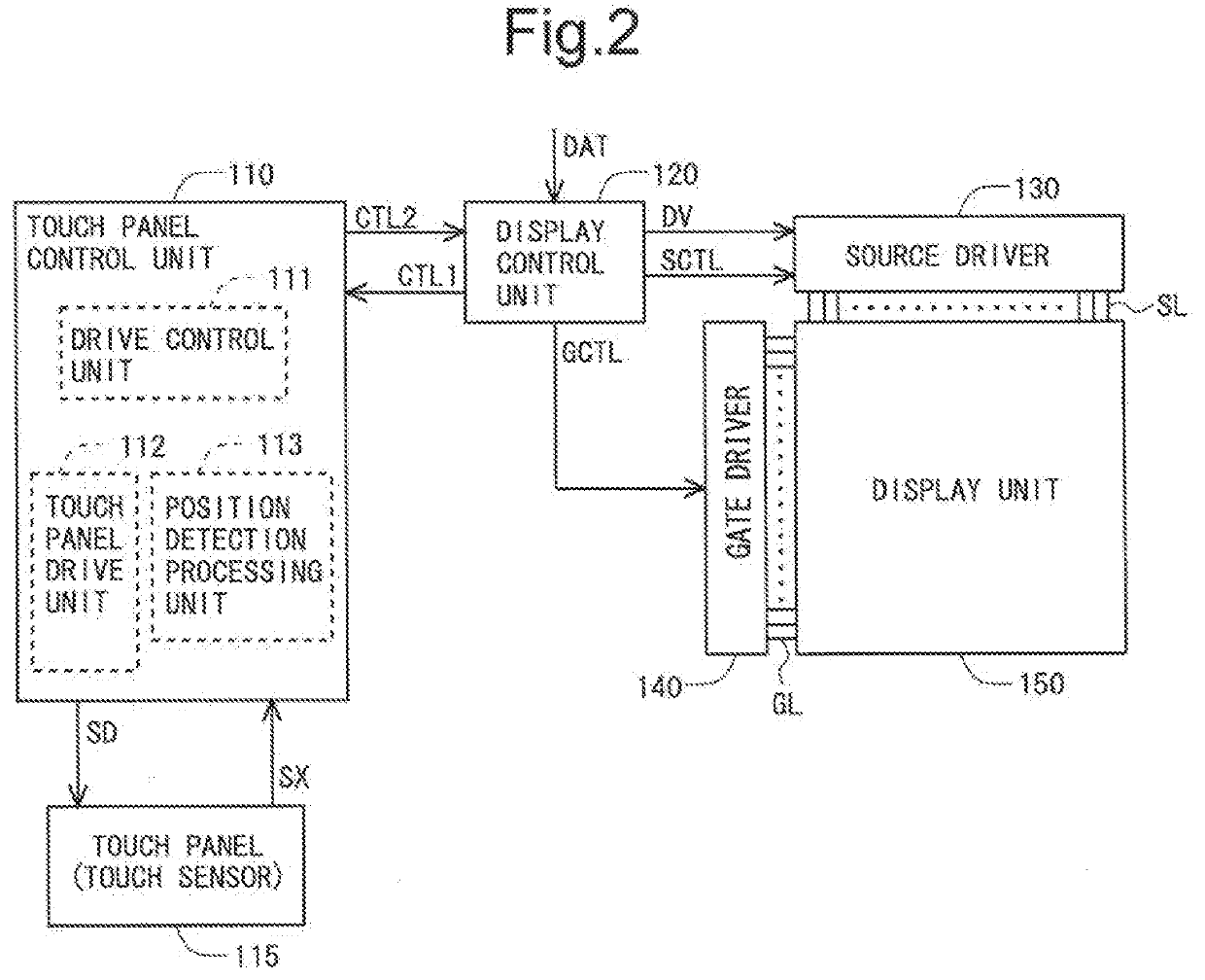
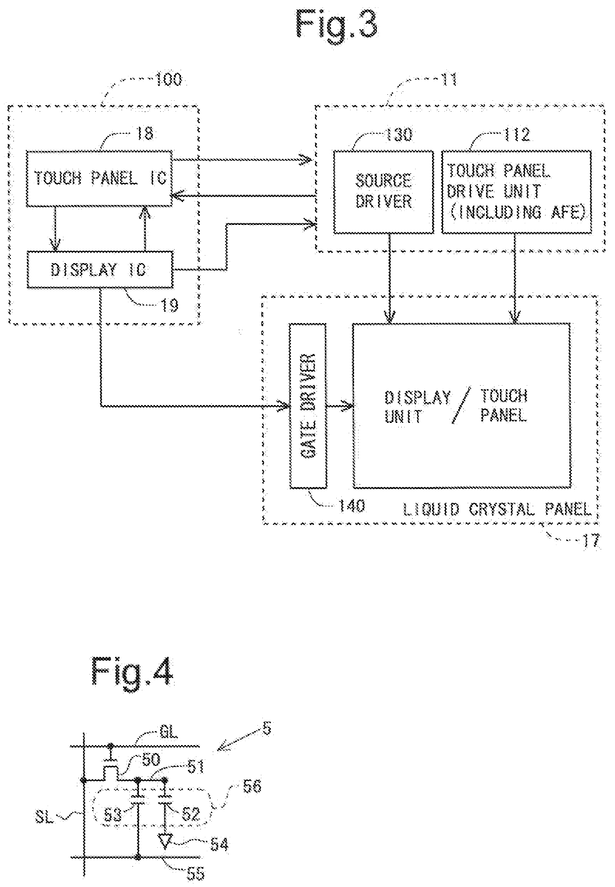
[0065]FIG. 2 is a block diagram for explaining a functional configuration of a liquid crystal display device with a built-in touch sensor according to an embodiment of the present invention. The liquid crystal display device includes a touch panel control unit 110, a touch panel (a touch sensor) 115, a display control unit 120, a source driver 130, a gate driver 140, and a display unit 150. The touch panel control unit 110 and the touch panel 115 are components related to touch detection, and the display control unit 120, the source driver 130, the gate driver 140, and the display unit 150 are components related to image display. It should be noted that, since FIG. 2 is the diagram showing the functional configuration, the positional relationship among the components is different from the actual one.

[0066]The touch panel control unit 110 includes a drive contr...


PUM


Abstract

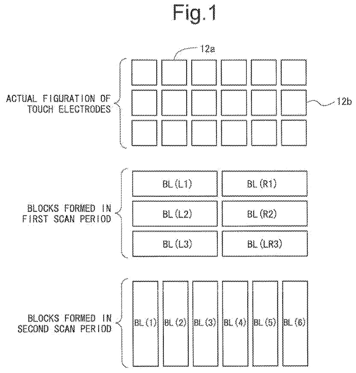
To realize a display device with a built-in touch sensor, the display device having a small-scale circuit and being capable of performing accurate touch detection even when an operation means except for a finger (e.g., stylus pen) is in use. When a detection target is an operation means except for a finger (e.g., stylus pen), touch detection is performed in a first scanning period in a state where each a plurality of sensor electrodes arranged side by side in a first direction (e.g., a direction in which scanning signal lines extend) are connected electrically, and touch detection is performed in a second scanning period in a state where each a plurality of sensor electrodes arranged side by side in a second direction (e.g., a direction in which video signal lines extend) are connected electrically.

Description

TECHNICAL FIELD[0001]The following disclosure relates to a display device with a built-in touch sensor and a drive method for the same, and more specifically relates to a display device with a built-in touch sensor, in which a common electrode being used for image display is also used as a sensor electrode (electrode for touch detection), and a drive method for the same.BACKGROUND ART[0002]A touch panel has been attracting attention as an input device for performing an operation in a computer system or the like. For example, in a capacitive-type touch panel, the position of an object to be detected, such as a finger of a user (operator) or a touch pen, is detected based on a change in electrostatic capacitance. Such a touch panel has hitherto been used as superimposed on a display panel such as a liquid crystal panel. Such a touch panel provided on the display panel is called an “out-cell type touch panel.” The out-cell type touch panel has, for example, a sensor pattern as shown in...

Claims


Application Information

Patent Timeline
IPC IPC(8): G06F3/041
CPCG06F3/04164G06F3/04162G06F2203/04114G06F2203/04104G06F3/0412G09F9/00G09G3/20G09G3/36G06F3/04166G06F3/0443G06F3/0446G06F3/044
Inventor MAYUMI, MASASHIMIYAZAKI, SHINICHI
Owner SHARP KK
Learn More