Method of operating a strip coiler and strip coiler operated thereby

A strip coiling machine and strip coiling technology, applied in the direction of winding mechanism, textile and papermaking, fiber processing, etc., can solve impossible and difficult problems, achieve quality improvement and reduce the risk of wear and tear

Active Publication Date: 2021-11-26
TRUETZSCHLER GRP SE
View PDF8 Cites 0 Cited by
  • Summary
  • Abstract
  • Description
  • Claims
  • Application Information

AI Technical Summary

Problems solved by technology

In particular, this makes it difficult or impossible to automatically attach one sliver end to another sliver end (also referred to as "auto-lapping") for continuous combing that overcomes sliver boundaries. not even possible

Method used


Image

  • Method of operating a strip coiler and strip coiler operated thereby
  • Method of operating a strip coiler and strip coiler operated thereby
  • Method of operating a strip coiler and strip coiler operated thereby

Examples


Embodiment Construction

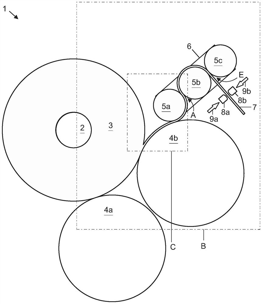
[0035] figure 1 A sliver coiler 1 according to a first embodiment of the invention is shown and has only the components which are essential for the invention. For the sake of clarity, other components such as creel, drafting device etc. are not shown.

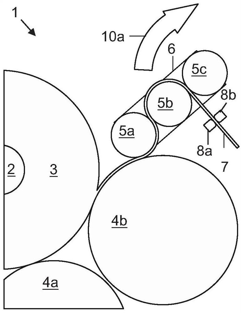
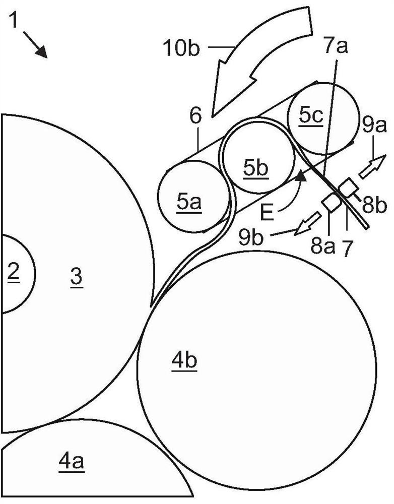
[0036] The sliver 7 comes from a drafting device (not shown), indicated here by the blank end on the right, and passes through a pressing device provided here with three pressing rollers 5 a - 5 c . The pressure rollers 5 a - 5 c are driven and freely rotatably mounted on the frame 6 in the usual manner. In this case, the pressure rollers 5 b , 5 c form, in their region facing the free end of the sliver 7 , the inlet E of the pressure roller arrangement. The sliver leaves the nip roll arrangement at outlet A of the arrangement and touches the nearest lap roller 4b of a not further indicated lap arrangement, here in the form of two lap rollers 4a, 4b form of the device. The sliver 7 passes through the lap rollers to the bobb...


PUM


Abstract

The invention relates to a method of operating a rod coiler (1), in which rod coils (3) of predetermined dimensions are first formed. A thin section (7a) is then formed in the sliver (7) between the device inlet of the pinch rollers (5a-5c) of the sliver coiler and a fixed position arranged upstream of the inlet in the direction of sliver transport. The sliver wound onto the bobbin ( 2 ) is then torn from the remaining sliver in the sliver winder in the region of the thin section. The strip coiler has a drafting unit and pinch rolls (5a‑5b). The pinch rollers are arranged and set up for consolidating the sliver coming from the drafting unit and feeding it to the lap unit (4a, 4b) of the sliver coiler. The lap device is in turn provided and set up for rotating the bobbin lying in the sliver transport direction (12) and for winding the sliver from the pressure roller device on the bobbin. The sliver coiler has a fastening device which is arranged at a fixed position and is designed to fix the incoming sliver or to release the sliver in the direction of sliver transport, depending on the operating state. The strip coiler was set up to operate according to the method described above.

Description

technical field [0001] The invention relates to a method for operating a coiler and a coiler operated thereby. Background technique [0002] Strip coilers are known per se. The strip winder introduces fiber strips from a plurality of cans, such as 24 cans, and places the fiber strips side by side as seen in the transport direction to form fiber strips, and drafts the fiber strips formed in this way in a drafting device. A flattened sliver is formed and transported in the sliver transport direction through a device with usually three nip rollers to a device with usually two lap rollers. The compression rollers consolidate the sliver coming from the drafting unit and squeeze out the air. The bobbin to be wrapped rests on the lap roller. The consolidated sliver from the pinch roll moves away from the pinch roll between lap rollers and bobbins. Due to the weight of the bobbins, the sliver reaches the surface of the bobbins, which are in rotation due to the friction of the la...

Claims


Application Information

Patent Timeline
Patent Type & Authority Patents(China)
IPC IPC(8): D01G27/00D01G27/02
CPCD01G27/00D01G27/02
Inventor 托马斯·施密茨
Owner TRUETZSCHLER GRP SE
Why Eureka
Try Eureka