Steering system

A steering system, axial end technology, used in steering mechanisms, mechanical steering gears, power steering mechanisms, etc., can solve problems such as steering system damage, simplify manufacturing, improve continuous load capacity, and avoid notch effects.

Inactive Publication Date: 2020-01-24
MIBA SINTER AUSTRIA
View PDF1 Cites 0 Cited by
  • Summary
  • Abstract
  • Description
  • Claims
  • Application Information

AI Technical Summary

Problems solved by technology

This subsequently leads to damage to the steering system

Method used


Image

  • Steering system
  • Steering system
  • Steering system

Examples


Embodiment Construction

[0025] At the outset, it should be pointed out that in the different described embodiments, identical parts are provided with the same reference symbols or the same component designations, wherein the disclosure contained in the entire description can be transferred to the reference symbols with the same reference symbols. Or on the same part with the same component name. The positional specifications selected in the description, such as top, bottom, sideways, etc., also refer to the directly described and illustrated figures and these positional specifications are transferred to the new position in the event of a position change.

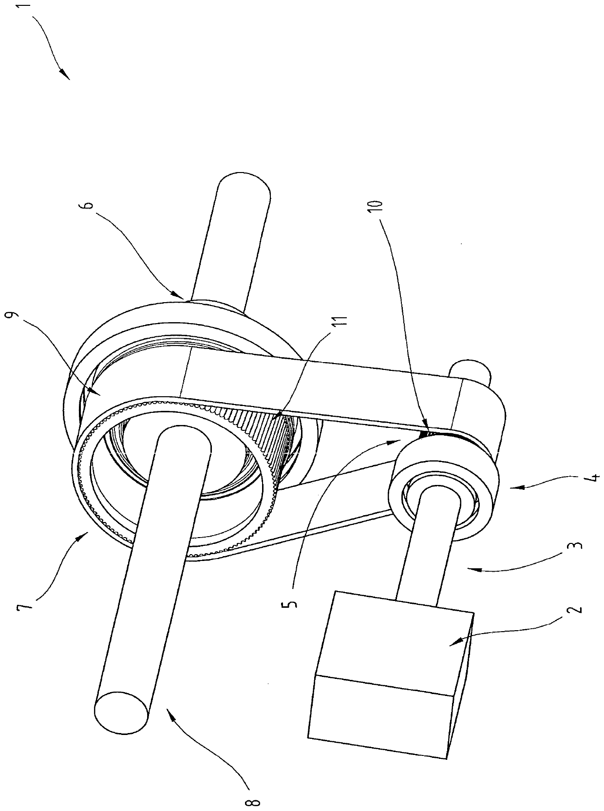
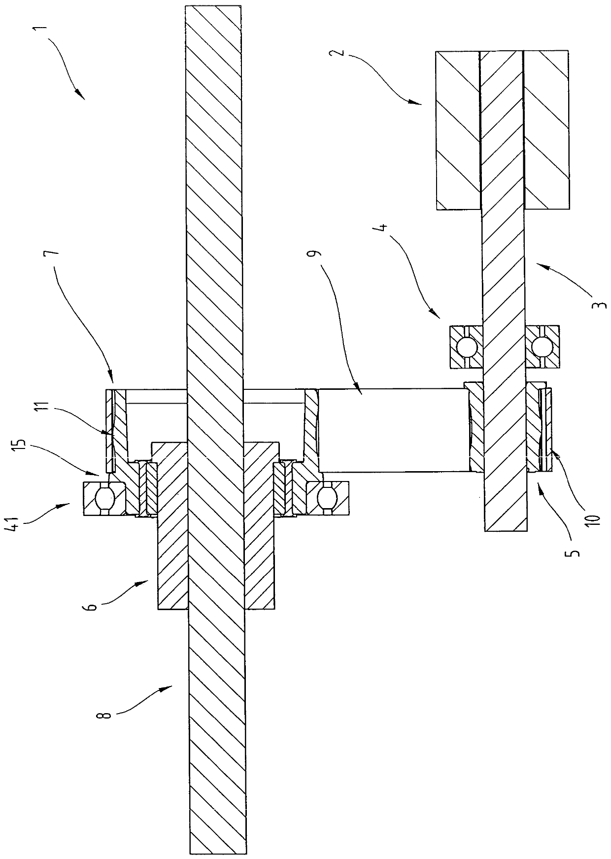
[0026] exist figure 1 and figure 2 A partial view of the steering system 1 , in particular of the EPS steering system 1 , is shown in oblique view or in section in side view. Only the details relevant for the description of the invention are shown in these two figures, since such steering systems are already known from the prior art and are desc...


PUM


Abstract

The invention relates to a steering system (1) comprising a motor (2) with a first belt pulley (5) and a recirculating ball drive (6) with a second belt pulley (7), wherein the first and the second belt pulleys (5, 7) are connected to one another via a belt. The first and / or second belt pulley (5, 7) comprise(s) an outer ring (12), an inner ring (13) and an intermediate ring (14), wherein the outer ring (12) preferably comprises an external toothing (1), the intermediate ring (14) is arranged between the outer ring (12) and the inner ring (13) in radial direction and connected to these, and the intermediate ring (14) at least partially consists of a rubbery-elastic material.

Description

technical field [0001] The invention relates to a steering system comprising a motor with a first reel and a recirculating ball drive with a second reel, wherein the first reel and the second reel are connected via a belt interconnected. Background technique [0002] It is known that, in servo steering systems, auxiliary drives are used to reduce the force to be used for steering. This is the electric drive in the so-called EPS steering system (Electric Power Steering Lenksysteme). There are different types of EPS steering systems, namely C-EPS systems (in which the servo unit is positioned in the steering train and transmits the rotational movement via a worm wheel), P-EPS systems (in which the servo unit is arranged on the steering drive pinion and separated The second pinion shaft is driven via a worm gear) and the R-EPS system (where the servo unit is positioned parallel or concentrically around the gear rod and the rotational movement is via a belt and recirculating b...

Claims


Application Information

Patent Timeline
IPC IPC(8): B62D5/04B62D3/08F16H7/02
CPCB62D3/08B62D5/0421B62D5/0448F16H7/02B62D5/0424F16H55/36F16H2055/366
Inventor K·斯蒂芬
Owner MIBA SINTER AUSTRIA
Why Eureka
Try Eureka