Turbine airfoil abradable coating system and corresponding turbine blades

A coating system and turbine technology, applied in the direction of machine/engine, mechanical equipment, engine components, etc., can solve the problems of the blade losing the ability to continue cutting, rapid decomposition, etc., to improve the clearance control ability, high thermal decomposition ability, The effect of reducing the risk of tip wear

Inactive Publication Date: 2015-07-08
SIEMENS ENERGY INC
View PDF9 Cites 0 Cited by
  • Summary
  • Abstract
  • Description
  • Claims
  • Application Information

AI Technical Summary

Problems solved by technology

However, many abrasive blade treatment materials break down rapidly when exposed to the hot gas environment of a gas turbine
Therefore, during the break-in period of the gas turbine, during a hot restart, the blades lose their ability to continue cutting

Method used


Image

  • Turbine airfoil abradable coating system and corresponding turbine blades
  • Turbine airfoil abradable coating system and corresponding turbine blades
  • Turbine airfoil abradable coating system and corresponding turbine blades

Examples


Embodiment Construction

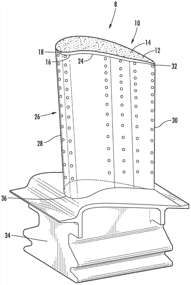
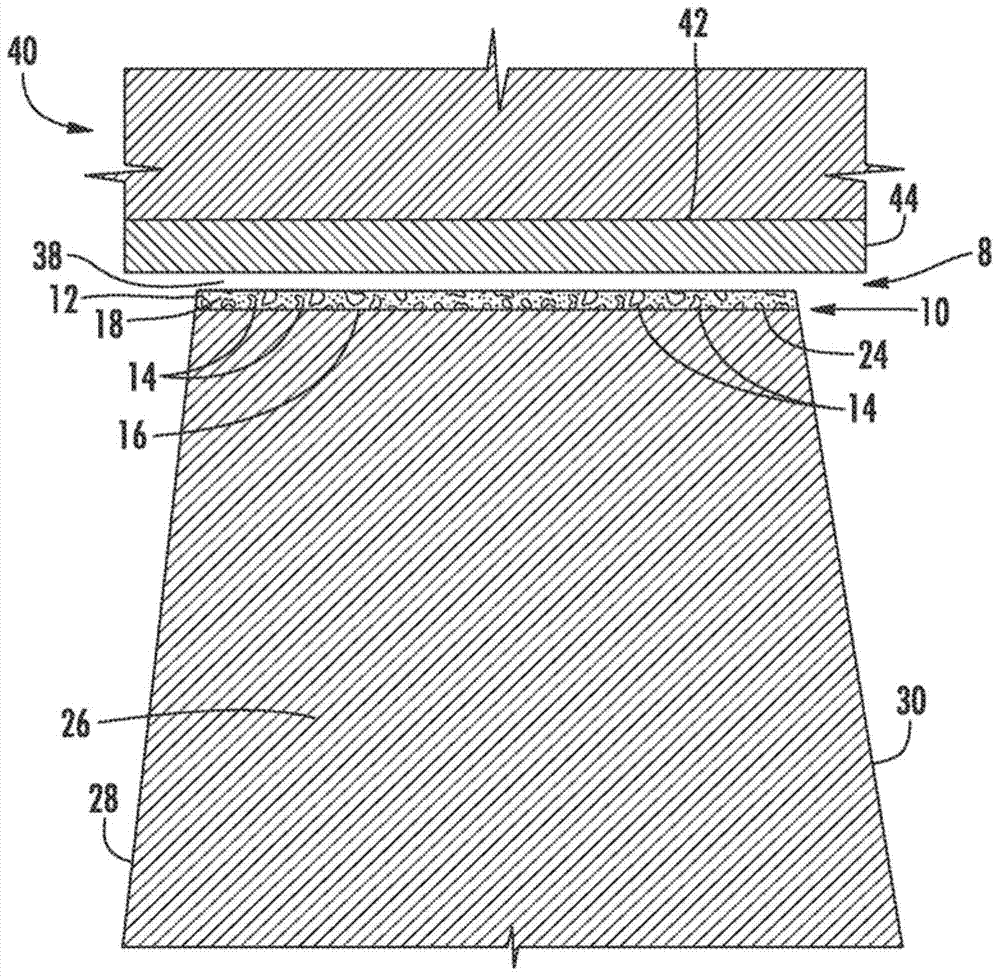
[0025] Such as Figure 1-7 As shown, the present invention discloses a turbine airfoil abradable coating system 8 having a grooved tip 10 having a coating 12 comprising an abrasive 14 . The grooved tip 10 may be attached to the radially outer surface 16 of the tip 24 and may be composed of at least one support material 18 comprising at least one abrasive particle 14 composed of a refractory carbide material that The material has a higher resistance to thermal decomposition than conventional tip abrasives and only negligibly reacts chemically with the metal elements in the metal substrate used to attach the abrasive 14, in at least one embodiment, The abrasive particles 14 may be tantalum carbide. The grooved tip 10 may also extend radially outward from the tip 24 and may cover at least a portion of the radially outer surface 16 of the tip 24 .

[0026] Such as figure 1 and figure 2 As shown, the grooved tip 10 may be attached to a radially outward tip 24 of a turbine buck...


PUM

PropertyMeasurementUnit
Sizeaaaaaaaaaa

Abstract

A squealer tip having a coating including an abrasive is disclosed. The squealer tip may be attached to a radially outer surface of the airfoil tip and formed from at least one support material including at least one abrasive particle formed from a refractory carbide material that has a better resistance to thermal degradation compared to conventional blade tip abrasive materials as well as negligible chemical reaction with metal elements in the metal matrix used to attach the abrasive. In at least one embodiment, the abrasive particle may be tantalum carbide. The squealer tip may also extend radially outward from the tip and cover at least a portion of the radially outer surface of the tip

Description

[0001] Statement Regarding Federally Funded Research or Development [0002] Development of this invention was supported in part by the US Department of Energy's Advanced Turbine Development Program under Contract No. DE-FC26-05NT42644. Accordingly, the US Government may have certain rights in this invention. technical field [0003] The present invention relates generally to turbine buckets, and more particularly to blade tips of turbine buckets. Background technique [0004] Generally, a gas turbine includes a compressor for compressing air, a combustor for mixing the compressed air with fuel and igniting the mixture, and a turbine bucket assembly for generating power. Combustion chambers often operate at high temperatures that can exceed 2500 degrees Fahrenheit. Typical turbine combustor configurations expose turbine bucket assemblies to such high temperatures. Therefore, turbine buckets must be made of materials that can withstand such high temperatures. [0005] Typ...

Claims


Application Information

Patent Timeline
IPC IPC(8): F01D11/12
CPCF01D11/122F05D2300/226
Inventor D.B.艾伦
Owner SIEMENS ENERGY INC
Why Eureka
Try Eureka