Flyback power-converting device with zero-voltage switching and method for flyback converting power with zero-voltage switching

a power conversion device and zero-voltage switching technology, applied in the field of power devices, can solve problems such as damage to internal components, and achieve the effects of reducing the impact of internal components, extending the service time of products, and increasing curren

Inactive Publication Date: 2020-08-06
CHICONY POWER TECH CO LTD
View PDF10 Cites 6 Cited by
  • Summary
  • Abstract
  • Description
  • Claims
  • Application Information

AI Technical Summary

Benefits of technology

[0009]In conclusion, according to the flyback power-converting device and the method for flyback converting power of the present invention, a surge current can be prevented from being generated on a secondary side when the clamp damping circuit releases energy via an auxi...

Problems solved by technology

However, when the auxiliary switch is working, a surge current i...

Method used


Image

  • Flyback power-converting device with zero-voltage switching and method for flyback converting power with zero-voltage switching
  • Flyback power-converting device with zero-voltage switching and method for flyback converting power with zero-voltage switching
  • Flyback power-converting device with zero-voltage switching and method for flyback converting power with zero-voltage switching

Examples


Embodiment Construction

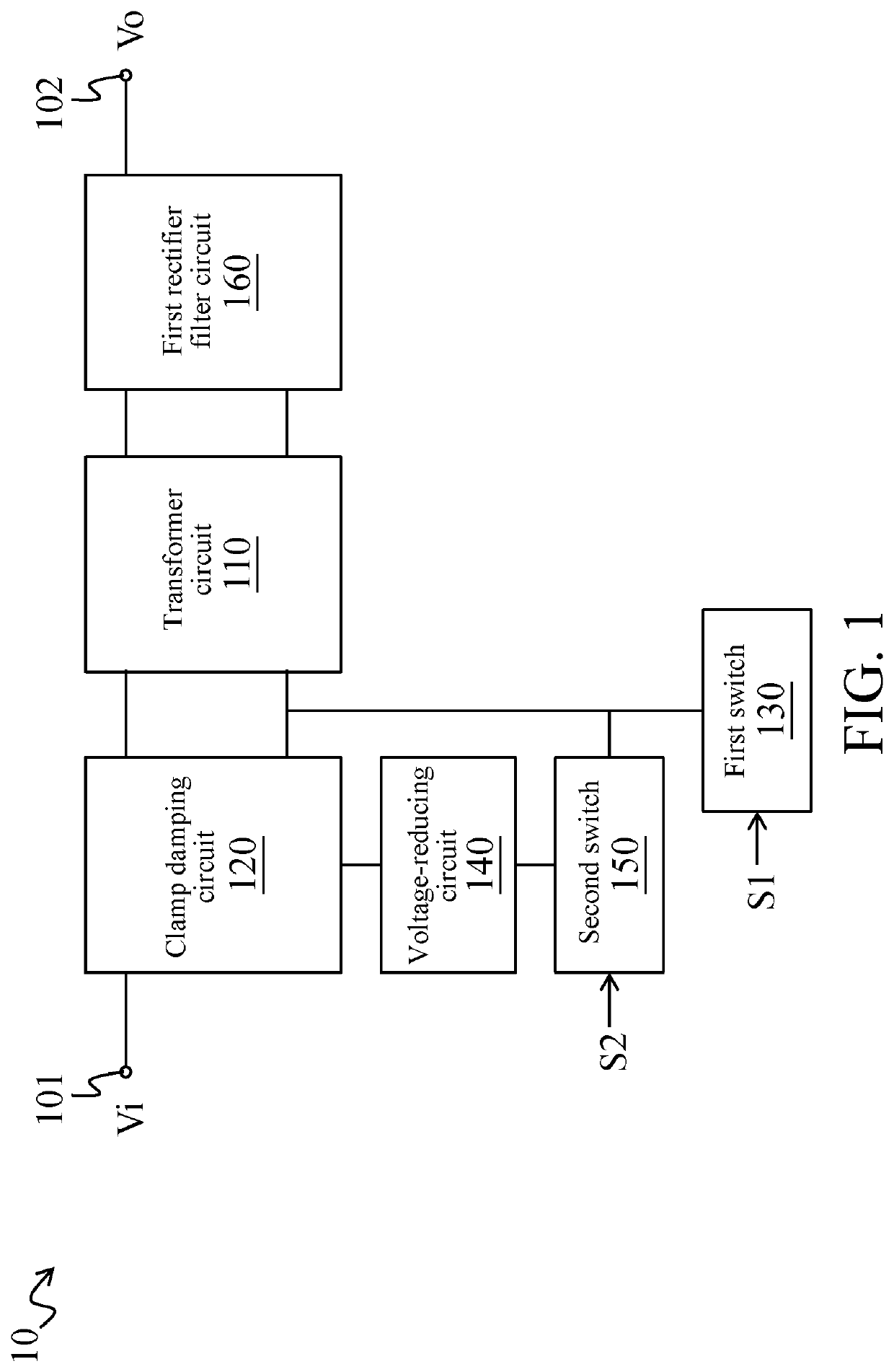
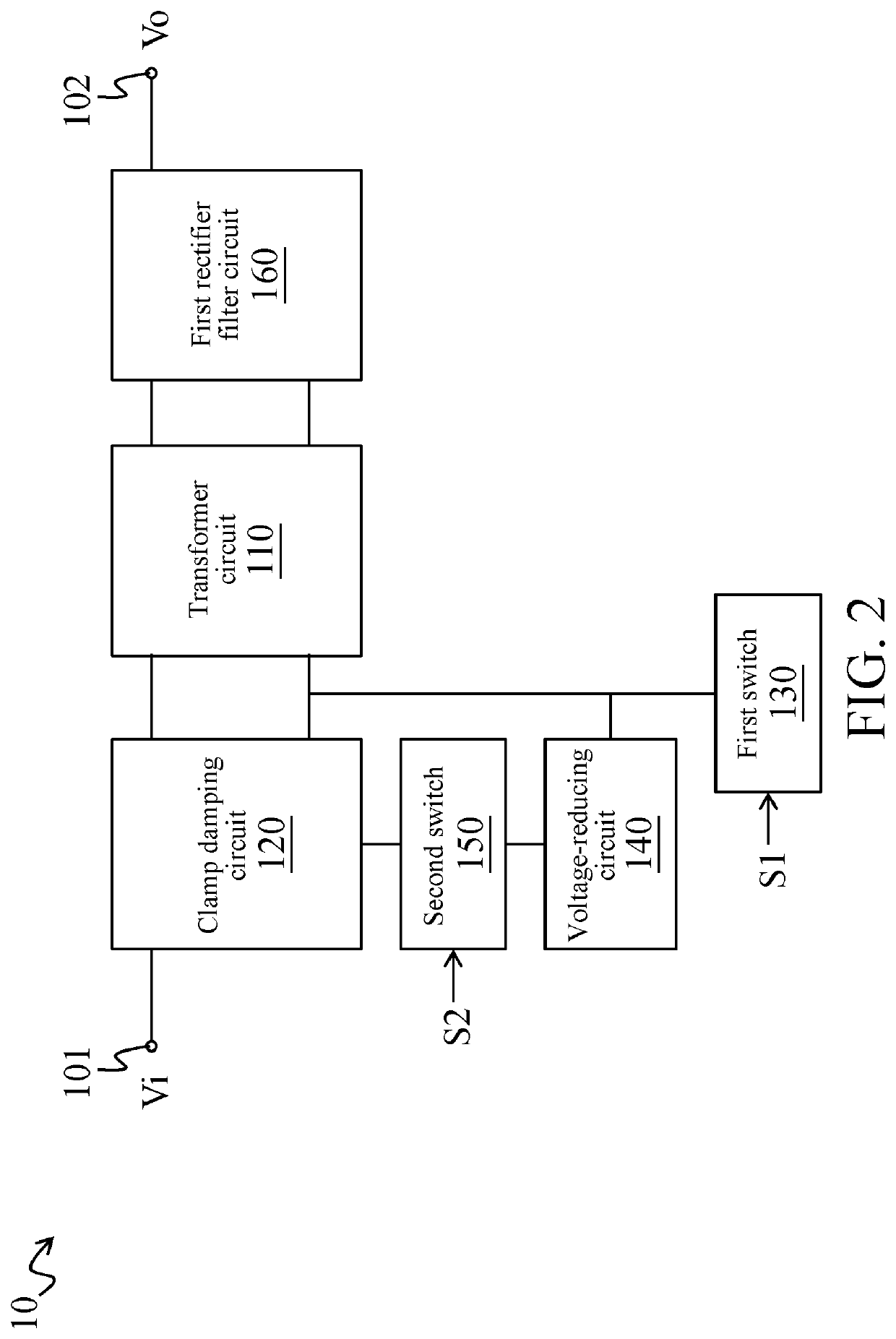
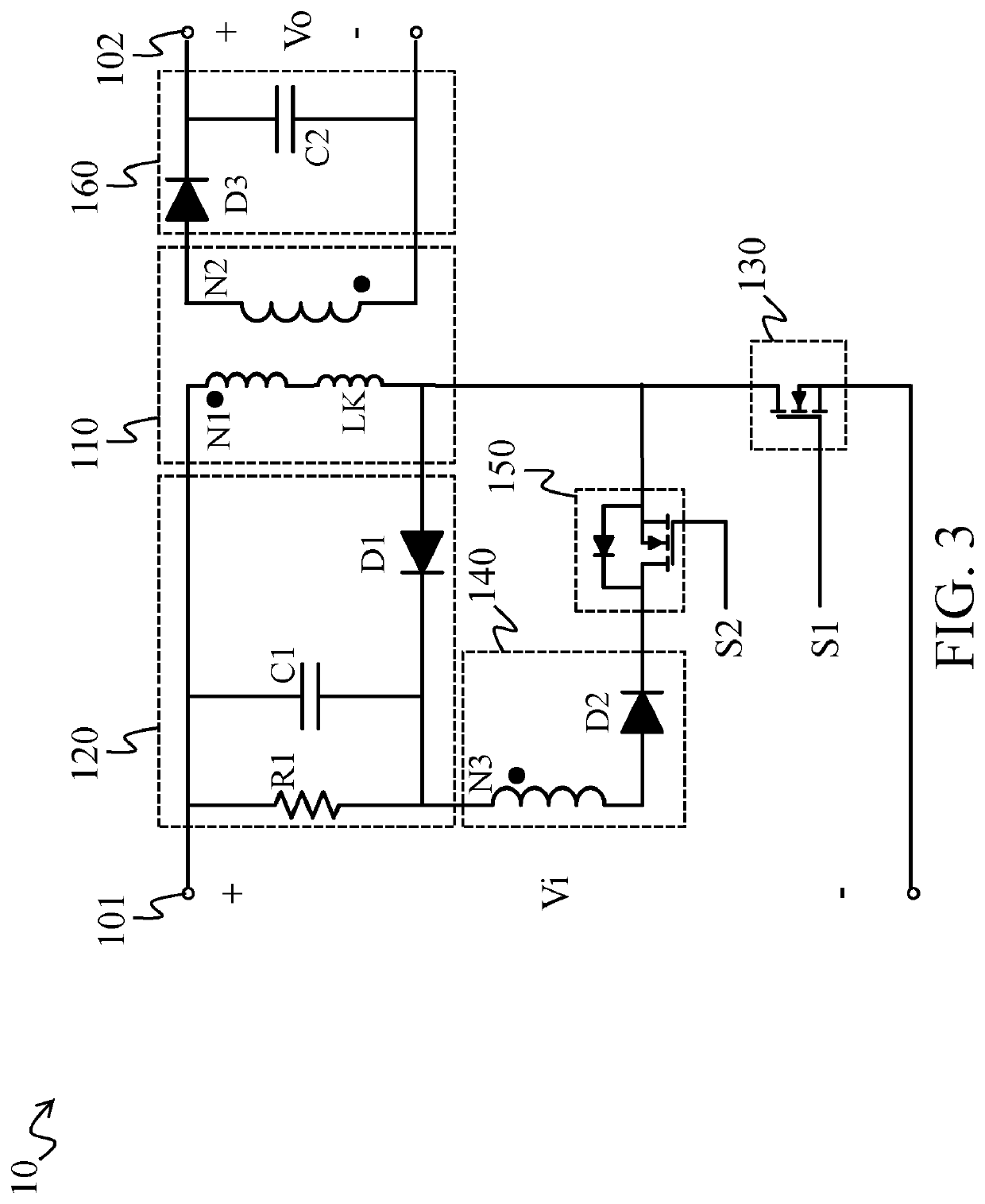
[0021]Referring to FIG. 1, a flyback power-converting device 10 includes a transformer circuit 110, a clamp damping circuit 120, a first switch 130, a voltage-reducing circuit 140 and a second switch 150.

[0022]The clamp damping circuit 120 is coupled to a primary side of the transformer circuit 110. In this case, the clamp damping circuit 120 is connected in parallel with the primary side of the transformer circuit 110, that is, the clamp damping circuit 120 is coupled between a first end and a second end of the primary side of the transformer circuit 110. In addition, the first end of the primary side of the transformer circuit 110 is further coupled to an input end 101.

[0023]The first switch 130 is coupled between the second end of the primary side of the transformer circuit 110 and a ground. In this case, through switching of the first switch 130, the transformer circuit 110 converts an input power Vi to generate a converted voltage (referred to as a first converted voltage below...


PUM


Abstract

A flyback power-converting device includes a transformer circuit, a clamp damping circuit, a first switch, a voltage-reducing circuit and a second switch. The clamp damping circuit and the first switch are coupled to the transformer circuit. The voltage-reducing circuit and the second switch are coupled in series between the clamp damping circuit and the transformer circuit. Through switching of the first switch, the transformer circuit converts an input power to generate a first converted voltage and to enable the clamp damping circuit to store an inductive energy. In addition, when the second switch is turned on, the clamp damping circuit releases the inductive energy to the transformer circuit via the voltage-reducing circuit, so that the transformer circuit generates a second converted voltage according to the inductive energy.

Description

CROSS-REFERENCES TO RELATED APPLICATIONS[0001]This application claims the priority benefit of U.S. provisional application Ser. No. 62 / 800,048, filed on Feb. 1, 2019 and Patent Application No. 108132489 filed in Taiwan, R.O.C. on Sep. 9, 2019. The entirety of the above-mentioned patent applications are hereby incorporated by references herein and made a part of the specification.BACKGROUNDTechnical Field[0002]The present invention relates to a power device, and in particular, to a flyback power-converting device and a method for flyback converting power.Related Art[0003]With the development of science and technology, electronic devices occupy an important position in our daily lives, and a main power source on which the electronic devices depend is still direct current power. However, a mains is mainly alternating current power. Therefore, the electronic devices are usually coupled to the alternating current power via an adapter, and a power-converting device in the adapter converts...

Claims


Application Information

Patent Timeline
IPC IPC(8): H02M3/335
CPCH02M3/33507H02M3/3353H02M3/28H02M3/33569H02M1/34H02M3/335H02M1/344
Inventor PENG, TSO-JENWANG, SSU-HAO
Owner CHICONY POWER TECH CO LTD
Why Eureka
Try Eureka