High-pressure pump

A technology for high-pressure pumps and pump pistons, applied to pumps, multi-cylinder pumps, fuel injection pumps, etc., to achieve the effect of reducing guide diameter and low cost

Active Publication Date: 2016-05-11
ROBERT BOSCH GMBH
View PDF10 Cites 0 Cited by
  • Summary
  • Abstract
  • Description
  • Claims
  • Application Information

AI Technical Summary

Problems solved by technology

However, this cannot always be ensured in relation to the guide diameter of the push rod body

Method used


Image

  • High-pressure pump
  • High-pressure pump
  • High-pressure pump

Examples


Embodiment Construction

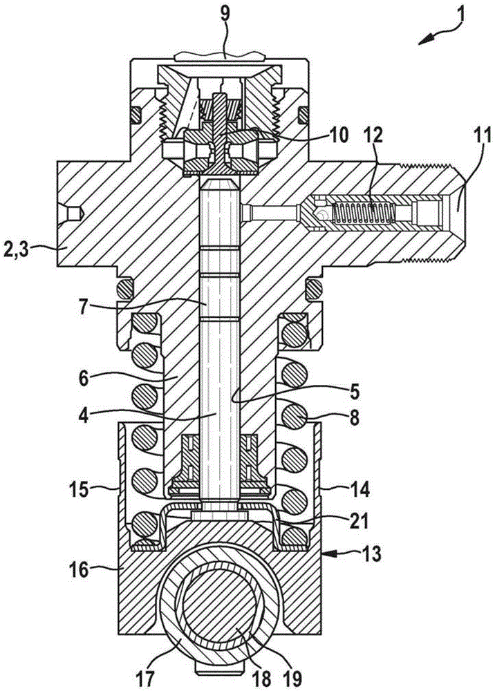
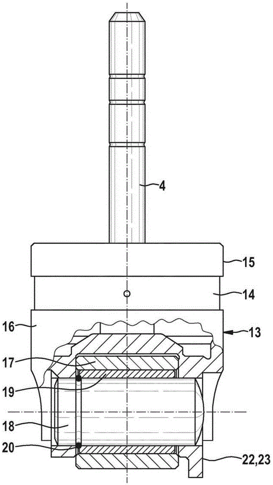
[0023] exist figure 1 A section through a high-pressure pump 1 for a fuel injection system, which is designed as a cartridge pump, is shown in . The high-pressure pump 1 shown here uses a common rail system. The high-pressure pump 1 has a pump housing 2 with a cylinder head 3 in which a pump element with a pump piston 4 is located, which is driven in rotation via a drive shaft (not shown here) ( see image 3 ) is indirectly driven to reciprocate in a direction at least approximately radial with respect to the axis of rotation of the drive shaft. The pump piston 4 is guided sealingly displaceably in the cylinder bore 5 in the section 6 of the cylinder head 3 and delimits a pump working chamber 7 in the cylinder bore 5 with the end face of the pump piston facing away from the drive shaft. A spring 8 is arranged around the circumference of the section 6 .

[0024] The pump working chamber 7 is supplied with fuel via a fuel inlet 9 from a fuel tank of a high-pressure fuel inje...


PUM


Abstract

The invention relates to a high-pressure pump for a fuel injection system of an internal combustion engine, wherein the high-pressure pump has at least one pump piston which is driven by the rotation of a drive shaft around a rotational axis in a reciprocating movement in the substantially radial direction with respect to the rotational axis of the drive shaft, via at least one eccentric or cam which is arranged on the drive shaft and via a tappet assembly which is arranged on the pump piston, wherein the tappet assembly has a tappet body and a cam roller, wherein an anti-rotation safeguard is provided for the stable orientation of the cam roller on the drive shaft.

Description

technical field [0001] The invention relates to a high-pressure pump for a fuel injection system of an internal combustion engine. Background technique [0002] In order to charge fuel at high pressure in common rail systems, for example in common rail systems, inter alia high pressure pumps are used which have one or more pump pistons which are driven from the drive shaft indirectly, for example via cams or eccentrics Offset in reciprocating motion to perform the intake and compression strokes, the cam or eccentric is in contact with the roller of the pushrod assembly. During the intake stroke, fuel is drawn into the pump working chamber of the high-pressure pump, and during the compression stroke, the drawn-in fuel is compressed and discharged at the high-pressure accumulator of the common rail system. In this case, such a high-pressure pump can be designed as a cartridge pump. [0003] A cartridge pump is described, for example, in DE 10 2008 041 383 A1 for storing high...

Claims


Application Information

Patent Timeline
Patent Type & Authority Patents(China)
IPC IPC(8): F04B1/04F04B1/053F02M37/04F02M63/02F02M59/10
CPCF01L2305/00F01L2307/00F02M59/102F04B1/0408F04B1/0417F04B1/0426F04B1/0439F04B1/053
Inventor A·舍茨M·舍特尔
Owner ROBERT BOSCH GMBH
Why Eureka
Try Eureka