Fuel assembly and spacer

A technology for positioning grids and fuel assemblies, applied in the field of nuclear power, can solve problems such as scratches, affecting the structural integrity of fuel rods, and prone to abrasion in the contact area, so as to avoid scratches, reduce the risk of abrasion, and improve safety.

Active Publication Date: 2020-09-29
GUANGDONG NUCLEAR POWER JOINT VENTURE +3
View PDF8 Cites 0 Cited by
  • Summary
  • Abstract
  • Description
  • Claims
  • Application Information

AI Technical Summary

Problems solved by technology

[0003] The existing spring is in contact with the fuel rod through the convex side. The contact between the fuel rod and the rigid convex spring in this structure is line contact or even point contact. When the fuel rod vibrates, the fuel rod and the spring or rigid spring will Convex contact areas prone to abrasion
[0004] The rigid-convex structure of the existing product rubs against the fuel rods when the fuel assembly is loaded into the fuel assembly grid, which will cause significant scratches on the surface of the fuel rods, which is an important risk affecting the structural integrity of the fuel rods

Method used


Image

  • Fuel assembly and spacer
  • Fuel assembly and spacer
  • Fuel assembly and spacer

Examples


Embodiment Construction

[0045] In order to have a clearer understanding of the technical features, purposes and effects of the present invention, the specific implementation manners of the present invention will now be described in detail with reference to the accompanying drawings.

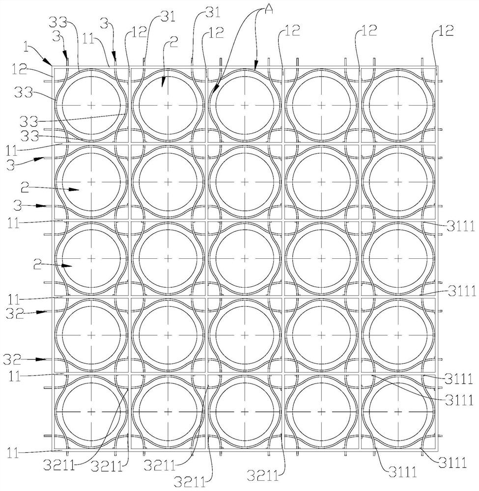
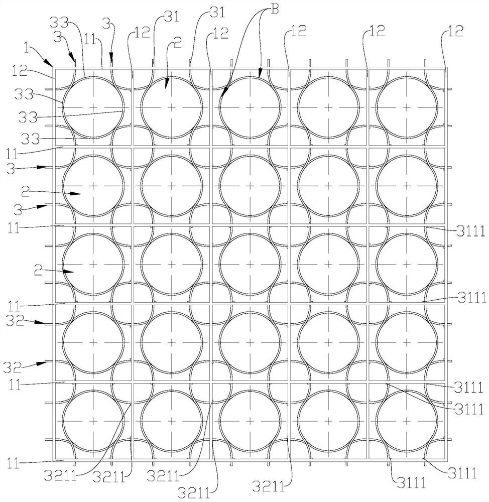
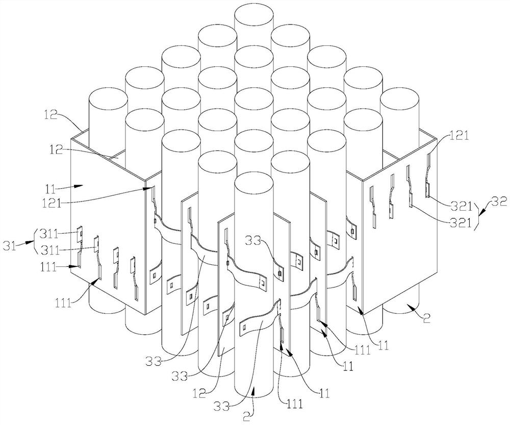
[0046] Such as Figure 1 to Figure 3 As shown, the fuel assembly in a preferred embodiment of the present invention includes a spacer grid 1 and a fuel rod 2, and the spacer grid 1 includes a plurality of first strips 11 arranged side by side at intervals and a plurality of second strips 12 arranged at intervals side by side, The first strip 11 and the second strip 12 cross each other to form a plurality of grids for the fuel rods 2 to pass through.

[0047] Further, the positioning grid 1 further includes an elastic clamping mechanism 3, and the elastic clamping mechanism 3 includes clamping portions 33 located in each grid.

[0048] The clamping portion 33 of the elastic clamping mechanism 3 can be switched between t...


PUM


Abstract

A fuel assembly and a positioning grid, comprising several first strips (11) arranged in parallel at intervals and several second strips (12) arranged in parallel at intervals, the first strips (11) intersecting the second strips (12) to form a grid for fuel rods (2) to be inserted, the positioning grid (1) also comprising an elastic clamping mechanism (3), the elastic clamping mechanism (3) comprising clamping parts (33) located within the grid, the clamping parts (33) of the elastic clamping mechanism (3) being capable of switching between first positions and second positions in the lateral direction of the grid. When in the first positions, the clamping parts (33) of the elastic clamping mechanism (3) form channels, larger than the outer diameter of the fuel rods (2), within the grid, and when in the second positions, the clamping parts (33) of the elastic clamping mechanism (3) clamp the fuel rods (2) inserted into the grid. The clamping parts (33) move in the lateral direction to clamp the fuel rods (2), so as to avoid scratching as the fuel rods (2) are inserted into the grid, reduce the risk of abrasion between the fuel rods (2) and the clamping system, form stable surface contact between the fuel rods (2) and the clamping system, and increase the safety of the fuel assembly.

Description

technical field [0001] The invention relates to the field of nuclear power, more specifically, to a fuel assembly and a positioning grid. Background technique [0002] A clamping system composed of a spring and a rigid convex structure is used in the existing fuel assembly positioning grid to maintain a stable position of the fuel rod in the fuel assembly. [0003] The existing spring is in contact with the fuel rod through the convex side. The contact between the fuel rod and the rigid convex spring in this structure is line contact or even point contact. When the fuel rod vibrates, the fuel rod and the spring or rigid spring will Convex contact areas are prone to abrasion. [0004] The rigid-convex structure of the existing product rubs against the fuel rods during the process of loading the fuel assembly into the fuel assembly grid, which will form significant scratches on the surface of the fuel rods, which is an important risk affecting the structural integrity of the ...

Claims


Application Information

Patent Timeline
Patent Type & Authority Patents(China)
IPC IPC(8): G21C3/352
CPCG21C3/34G21C3/352Y02E30/30
Inventor 颜景文刘雨利刘贻潮李伟才庞铮铮张玉相
Owner GUANGDONG NUCLEAR POWER JOINT VENTURE
Why Eureka
Try Eureka