Fluid ejecting apparatus and control method thereof

Inactive Publication Date: 2008-10-30
SEIKO EPSON CORP
View PDF3 Cites 3 Cited by
  • Summary
  • Abstract
  • Description
  • Claims
  • Application Information

AI Technical Summary

Benefits of technology

[0013]With this configuration, a capping operation is performed for each of the caps such that at least two caps are brought into contact with the fluid ejecting head at different times. Accordingly, the load on the driving source that occurs when the caps come into contact with the fluid ejecting head is reduced, when compared to configurations where all of the caps are brough

Problems solved by technology

One disadvantage of this system, however, is that when the plurality of caps simultaneously come into contact with the liquid ejecting head, an excessive load may be imposed on the driving source, which may cause problems.
More specifically, a large load may be generated on the driving

Method used


Image

  • Fluid ejecting apparatus and control method thereof
  • Fluid ejecting apparatus and control method thereof
  • Fluid ejecting apparatus and control method thereof

Examples


Example

First Embodiment

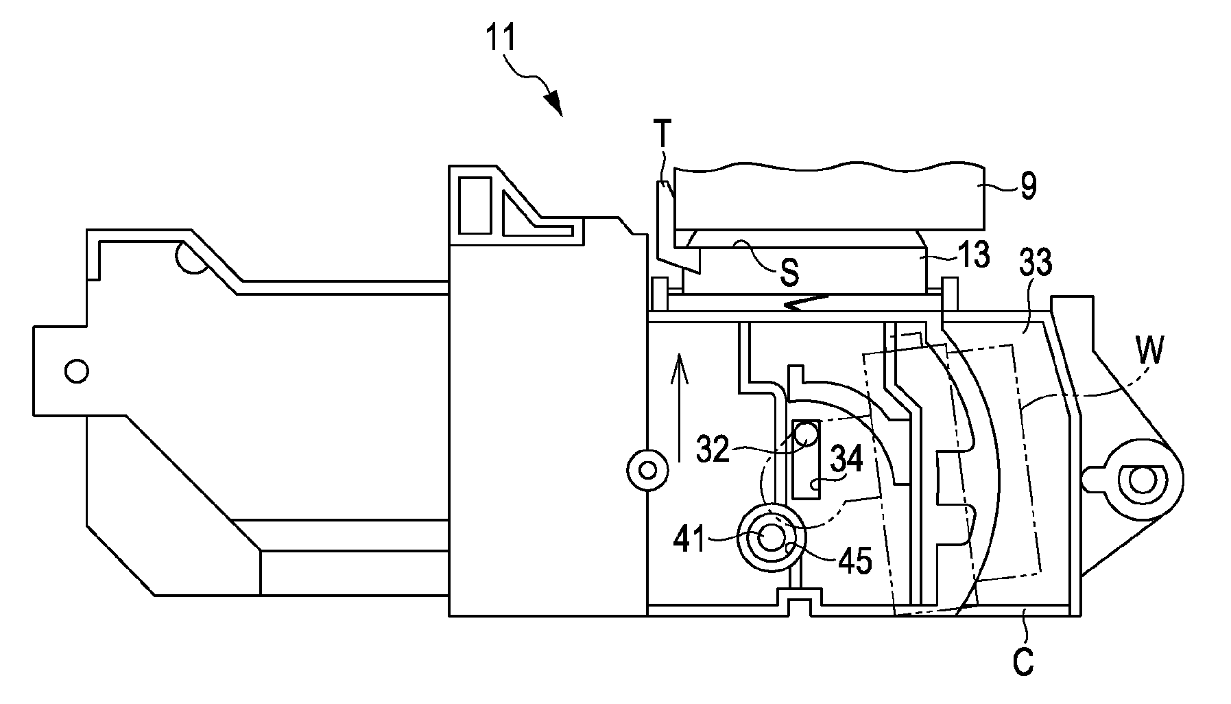
[0070]FIG. 13 is a diagram showing the relationship between a recording head and a cap in a first embodiment of the invention. In the first embodiment, as shown in FIG. 13, a cap array 13G having Q (where Q is an integer of 3 or more) cap members 13 is arranged to face a nozzle forming surface 91. Specifically, five cap members 13a to 13e are arranged to face the nozzle forming surface 91 of the recording head 9. For each of the cap members 13a-13e, a slider 12 and a cam mechanism 40 are provided. The slider 12 and the cam mechanism 40 provided for each of the cap members 13a-13e have the same configuration as those shown in FIGS. 6 to 8. In this specification, to clearly state which of cap members 13a-13e each member corresponds to, the alphabetic character of the corresponding cap member 13 is appended to the end of the reference numeral of each member. That is, the cam mechanisms 40, which correspond to each of the cap members 13a to 13e, are referred to as cam me...

Example

Second Embodiment

[0101]FIG. 16 is a diagram showing the configuration of a cam according to a second embodiment of the invention. The second embodiment differs from the first embodiment in the configuration of the cam, while other parts of the second embodiment are the same as those in the first embodiment. Hereinafter, only the configuration of the cam will be described, and the descriptions of the parts other than the cam will be omitted.

[0102]A cam CM1 shown in the row entitled CAM MECHANISMS 40a AND 40e” of FIG. 16 is a cam that is provided in the cam mechanisms 40a and 40e. That is, the cam CM1 corresponds to the cam 43a, 44a, 43e, or 44e. A curved surface CV1 is formed at the side surface of the cam CM1 from the bottom point BP to the top point TP. In addition, the relative distance between the contact shafts U1 and U2, which come into contact with the top point TP, and the shaft 41 is the relative distance d31. That is, in each of the cam mechanisms 40a and 40e, the relative ...


PUM


Abstract

A liquid ejecting apparatus with a capping mechanism capable of performing a capping operation to cap the nozzle openings of a liquid ejecting head wherein groups of symmetrically arranged caps are moved toward the nozzle openings in a series of predetermined intervals so as not to apply an excessive load on the liquid ejecting head.

Description

[0001]The entire disclosures of Japanese Patent Application No. 2007-117257, filed Apr. 26, 2007 is expressly incorporated herein by reference.BACKGROUND OF THE INVENTION[0002]1. Technical Field[0003]The present invention relates to a liquid ejecting apparatus that is capable of ejecting a fluid or liquid from a plurality of nozzle openings. More particularly, the present invention relates to a system and method of enclosing the nozzle openings with a cap when the nozzle openings are not performing a liquid ejecting operation.[0004]2. Related Art[0005]One example of a commonly used liquid ejecting apparatus is an image recording apparatus, such as an ink jet printer, which discharges and deposits ink droplets onto a recording medium, such as a recording paper or the like, to perform a recording operation. In recent years, however, liquid ejecting apparatuses have been increasingly used in various other manufacturing apparatuses, beyond image recording apparatuses. For example, other...

Claims


Application Information

Patent Timeline
IPC IPC(8): B41J2/165
CPCB41J2/16547
Inventor TAKAHASHI, NOBUHITO
Owner SEIKO EPSON CORP
Why Eureka
Try Eureka