Heat Cloth and Process for Producing the Same

a technology of heat cloth and heat shrink, applied in the field of heat cloth, can solve the problems of easy drop, difficult bonding retention, strong uncomfortable feeling in wearing, etc., and achieve the effects of reducing flexibility, good flexing properties, and thin and flexibl

Inactive Publication Date: 2008-10-16
MYCOAL PRODS CORP
View PDF32 Cites 28 Cited by
  • Summary
  • Abstract
  • Description
  • Claims
  • Application Information

AI Technical Summary

Benefits of technology

[0036]An object of the invention is to solve the foregoing problems and to provide a heat cloth which is thin and flexible; even when as a reaction of an air-permeable heat cloth proceeds, a heat generating composition becomes massive so that flexibility is lowered, or a part of an accommodating bag rides up by shrinkage and curling as caused by heat generation, well keeps the bonding and holding state so that it does not fall off easily; is supple like cloths; is excellent in flexing properties; easily and surely fits to flexible places such as elbows and knees; is able to take warmth; is applicable with good follow-up deformation properties to various places of a human body such as curved parts including shoulders, arms, a neck and feet; and hardly causes an uncomfortable feeling and a process for producing the same.

Problems solved by technology

However, following spreading in utilization of throwaway body warmers which are aimed to be applied to various places of a human body such shoulders, arms, a neck and feet, even if a heat generating composition is hardened by a thickener, etc., there were encountered problems that in a single packed state, for example, bonding retention is difficult so that the dropping easily occurs and that a strong uncomfortable feeling is caused in wearing.
Such problems are promoted due to a lowering of flexibility as caused by blocking following progression of a reaction of heat generating body.
There was also encountered a problem that a stretched film which forms an accommodating bag is shrunk and curled due to heat generation so that an end part of a single packaging bag rides up, whereby a body warmer as bonded and held easily peels away and drops due to catch therein.
Furthermore, even if the exothermic part is divided into plural compartments, a heat generating composition as hardened by a flocculant aid, etc. involved a problem that an exothermic performance is deteriorated.
That is, according to a method for filling a powdered heat generating composition or a granular heat generating composition while partially sealing, it was mechanically substantially impossible to produce a heat generating body having a plural number of small-sized sectional regions, and additionally, there was caused a problem due to shortage in sealing as caused by incorporation of the heat generating composition into a seal part or the like.
In particular, it was substantially impossible to continuously produce one having a partial shape having a size of not more than 20 mm or one having a small shape of not more than 20 mm.
Furthermore, according to a method using a rotary magnet system as disclosed in Patent Document 17, not only a complicated operation is necessary, but also its structure is complicated.
Accordingly, there were encountered problems that the operation at the time of forming an exothermic layer is troublesome and that a device to be used is complicated and expensive, is liable to cause a fault, takes a long time to do the maintenance and is inconvenient for handling.
Therefore, there was a limit in making the size of the exothermic part small.
Now, in comparison with a heat generating body in which a flocculant and a binding agent are not incorporated, in a heat generating body having plural sectional exothermic parts, the exothermic time is markedly short, especially, in a sectional exothermic part having a narrow region whose shortest length is not more than 15 mm or a sectional exothermic part of a small size, the exothermic duration is markedly short, resulting in a problem in view of practical use.
If it is intended to prolong the exothermic duration, there was a problem that it becomes necessary to increase the dimensions of a single sectioned exothermic part so that the heat generating body becomes one having a sectional exothermic part of a large size.
Furthermore, even by using a powdered or granular heat generating composition, there was a problem that a concave pocket must be previously provided in a packaging material, thereby bringing a complicated operation.
Thus, the process became complicated and involved a problem in view of costs.

Method used


Image

  • Heat Cloth and Process for Producing the Same
  • Heat Cloth and Process for Producing the Same
  • Heat Cloth and Process for Producing the Same

Examples


example 1

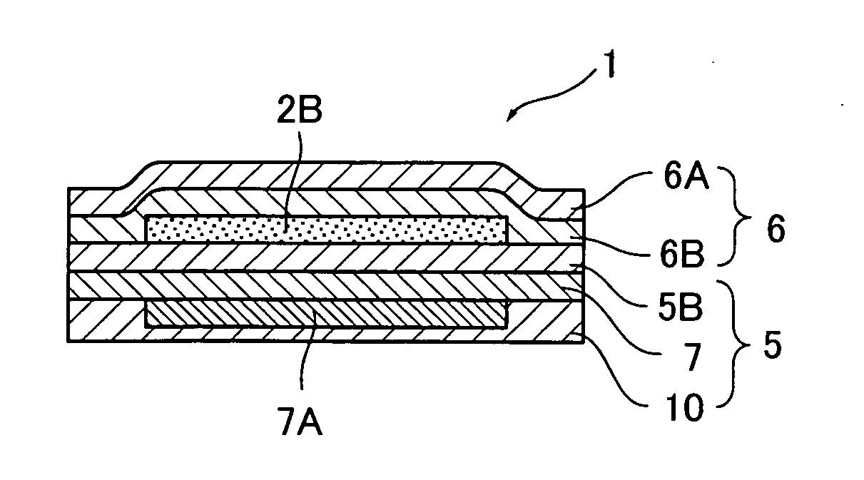
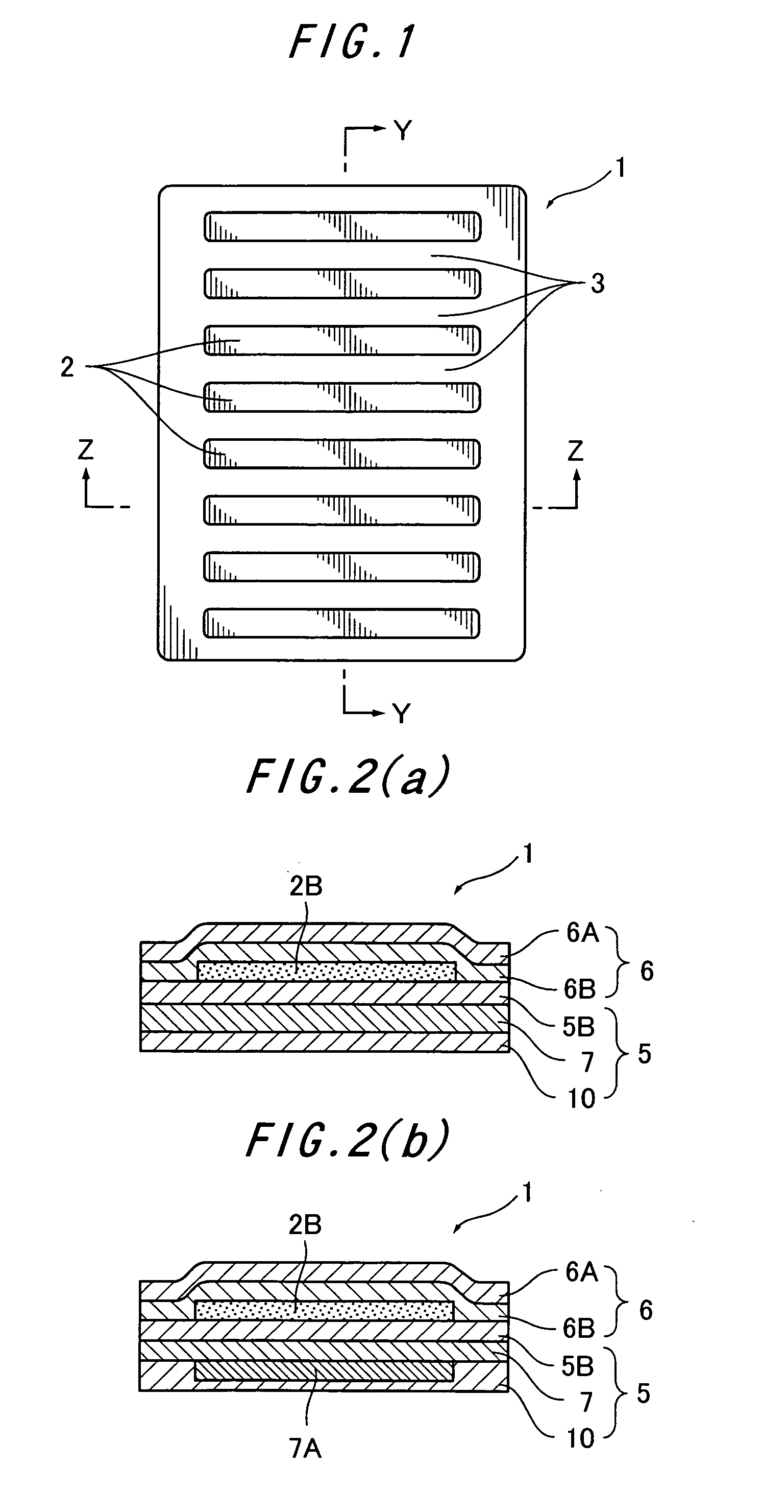
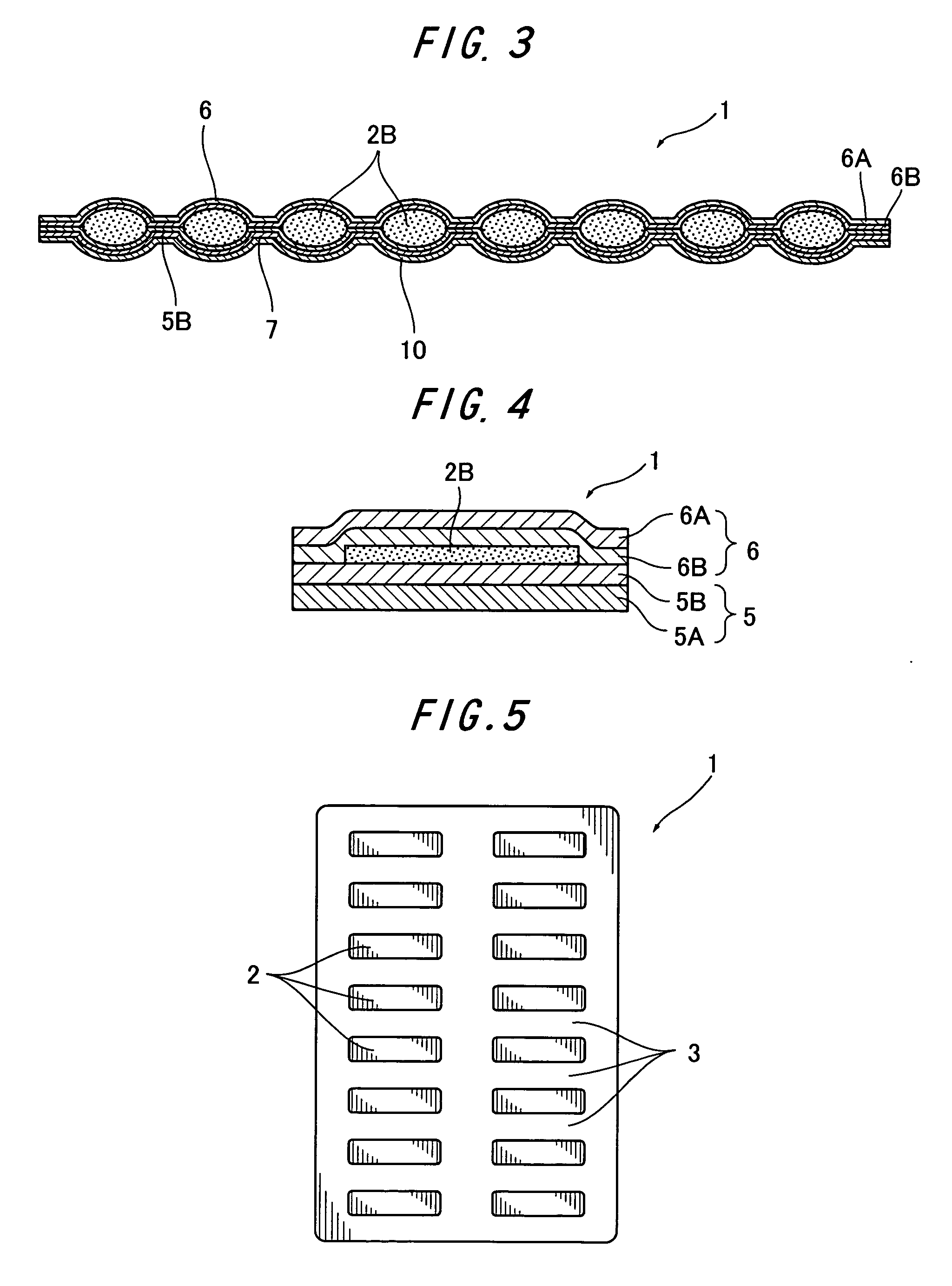
[0444]A heat generating composition having a water mobility value of 10, which is a mixture consisting of 100 parts by weight of a reduced iron powder (particle size: not more than 300 μm)), 7.0 parts by weight of active carbon (particle size: not more than 300 μm), 5.0 parts by weight of a wood meal (particle size: not more than 300 μm), 0.8 parts by weight of a water absorptive polymer (particle size: not more than 300 μm), 0.2 parts by weight of calcium hydroxide, 0.7 parts by weight of sodium sulfite and 11% of salt water, was used.

[0445]Next, as shown in FIG. 1, FIG. 2(a) and FIG. 3, by using the heat generating composition, heat generating composition molded bodies 2B were provided on the surface of a polyethylene film 5B of a substrate 5 made of the polyethylene film 5B provided with a 30 μm-thick acrylic adhesive layer 7 provided with a separator 10 by force-through molding using a trimming die having eight cavities of 5 mm in width×80 mm in length at intervals of 5 mm, so a...

example 2

[0452]A batchwise stirring tank composed of a mixer equipped with a rotary blade in a blade form of a ventilation fan was used as an oxidizing gas contact treatment device, and air was used as an oxidizing gas. First of all, a reaction mixture consisting of 100 parts by weight of a reduced iron powder (particle size: not more than 300 μm) and 5 parts by weight of 11% salt water and having a water mobility value of not more than 0.01 was charged in the contact treatment device vessel. Next, the upper portion of the contact treatment device vessel was opened to air, and the reaction mixture was subjected to self heat generation with stirring in the opened state to air under circumstances at 20° C. After about 20 seconds, at a point of time when the temperature rise of the reaction mixture reached 15° C., the reaction mixture was sealed in an air-impermeable accommodating bag and cooled to room temperature, thereby obtaining a heat generating mixture. The heat generating mixture had a ...

example 3

[0458]By using the same heat generating composition, substrate and covering material as in Example 1, except for changing the reduced iron powder of Example 1 to an iron powder (particle size: not more than 300 μm) containing 2% by weight of a carbon component resulting from a coating treatment of sponge iron with active carbon, heat generating composition molded bodies were molded by force-through molding using a trimming die having twelve cavities of 5 mm in width×80 mm in length at intervals of 7 mm, laminated on the substrate and covered by the covering material; the peripheries of the heat generating composition molded bodies 2B were sealed in a seal width of 5 mm to form a sectioned part 3; the periphery of a heat cloth 1 was sealed in a seal width of 8 mm; and a perforation 4 which can be cut by hand was provided in the sectioned part 3, thereby obtaining a heat cloth 1 provided with the perforation 4 of 153 mm in length×98 mm in width having twelve rectangular sectional exot...


PUM

PropertyMeasurementUnit
volumeaaaaaaaaaa
heightaaaaaaaaaa
widthaaaaaaaaaa

Abstract

To provide a heat cloth which is thin and flexible; even when as a reaction of an air-permeable heat cloth proceeds, a heat generating composition becomes massive so that flexibility is lowered, or a part of an accommodating bag rides up by shrinkage and curling as caused by heat generation, well keeps the bonding and holding state so that it does not fall off easily; is supple like cloths; is excellent in flexing properties; easily and surely fits to flexible places such as elbows and knees; is able to take warmth; is applicable with good follow-up deformation properties to various places of a human body such as curved parts including shoulders, arms, a neck and feet; and hardly causes an uncomfortable feeling and a process for producing the same.
A heat cloth having a heat generating composition molded body resulting from molding a heat generating composition containing surplus water as a connecting substance accommodated in an accommodating bag, wherein the accommodating bag is constituted of a substrate and a covering material; the covering material covers the heat generating composition molded body as provided on the substrate; the periphery of the heat generating composition molded body is heat sealed to form irregularities; sectional exothermic parts of a convex in which the heat generating composition molded body is accommodated are disposed while holding a sectioned part of a concave as a heat seal part; and the exothermic part is formed of a gathering of the sectional exothermic parts, which is characterized in that the substrate is substantially planar and does not contain a pocket, an accommodating division or an accommodating section; that the heat generating composition contains, as essential components, an iron powder, a carbon component, a reaction accelerator and water, does not contain a flocculant aid, a flocculant, an agglomeration aid, a dry binding material, a dry binding agent, a dry binder, a sticky raw material, a thickener and an excipient, contains surplus water so as to have a water mobility value of from 0.01 to 20, with the water in the heat generating composition not functioning as a barrier layer, and is capable of causing an exothermic reaction upon contact with air; that a volume of the heat generating composition molded body is from 0.1 to 30 cm3; that a capacity of the sectional exothermic parts to a ratio of the volume of the heat generating composition molded body is from 0.6 to 1.0; that a maximum height of the sectional exothermic parts is from 0.1 to 10 mm; that a width of the sectioned part as a space between the sectional exothermic parts is from 0.3 to 50 mm; that a minimum bending resistance on the surface orthogonal to at least a thickness of the heat cloth is not more than 100 mm; that a part of the accommodating bag has air permeability; and the surroundings of the accommodating bag are sealed.

Description

TECHNICAL FIELD[0001]The present invention relates to a heat cloth using a heat generating composition which after producing a heat generation composition molded body, is capable of causing heat generation without moving water in the heat generating composition molded body to a packaging material or a water absorptive sheet, the heat cloth being soft like fabrics and excellent in flexing properties, easily and surely fitting to flexible places such as elbows and knees, being able to take warmth, being applicable with good follow-up deformation properties to various places of a human body such as curved parts including shoulders, arms, a neck and feet and hardly causing an uncomfortable feeling, and to a process for producing the same.BACKGROUND ART[0002]Heat generating compositions utilizing an oxidation reaction of a metal such as iron have been provided as a powder or granule, or a viscous material or creamy material. Heat cloths utilizing such a heat generating composition are ve...

Claims


Application Information

Patent Timeline
Patent Type & Authority Applications(United States)
IPC IPC(8): F24J1/00F24V30/00
CPCA61F7/034A61F2007/0098Y10T156/10C09K5/18F24J1/00A61F2007/0268F24V30/00
Inventor DODO, TOSHIHIRO
Owner MYCOAL PRODS CORP
Why Eureka
Try Eureka