Ultrasonic probe

a technology of ultrasonic probes and probes, applied in the field of ultrasonic probes, can solve the problems of difficult handling of fragile ceramic materials, high processing costs, and inability to form tight curves of conventional ultrasonic transducer arrays made of ceramic materials, and achieve the effect of thin and flexible, increasing the resolution obtainabl

Inactive Publication Date: 2014-02-06
GENERAL ELECTRIC CO
View PDF2 Cites 2 Cited by
  • Summary
  • Abstract
  • Description
  • Claims
  • Application Information

AI Technical Summary

Benefits of technology

[0006]An array of ultrasonic transducers formed on a flexible piezoelectric polymer foil is disclosed. Ultrasonic transducer electrodes are formed on a first side of the foil and a ground layer is formed on a second side of the foil. An advantage that may be realized in the practice of some disclosed embodiments of a probe made from such an arrangement of ultrasonic transducers is the clear detection of smaller flaws in test objects than were capable of detection heretofore. The use of a flexible piezoelectric polymer foil means that it can be regulated to emit ultrasonic energy at higher frequencies in order to detect minute flaws. Another advantage that may be realized in the practice of other disclosed embodiments of such ultrasonic transducers is the wider range of probe contours that can be formed in order to accommodate testing of smaller objects. A piezoelectric polymer foil, such as polyvinylidenfluorid (“PVDF”), is sufficiently thin and flexible that it can be made to vibrate at higher ultrasonic frequencies, thereby increasing the resolution obtainable from ultrasonic testing. It is also flexible enough so that it can be attached to a probe structure having corners or other tight curvatures.

Problems solved by technology

In order to vibrate at extremely high frequencies to detect very small anomalies, a ceramic layer, which is typically rigid, must be manufactured as a very thin layer, which may not be feasible, and so makes the process expensive and the fragile ceramic material difficult to handle.
Moreover, small test objects may also require a test apparatus having an array of ultrasonic transducers that is tightly curved.
A conventional ultrasonic transducer array made of ceramic material is not capable of being formed in a tight curve.

Method used


Image

  • Ultrasonic probe
  • Ultrasonic probe
  • Ultrasonic probe

Examples


Embodiment Construction

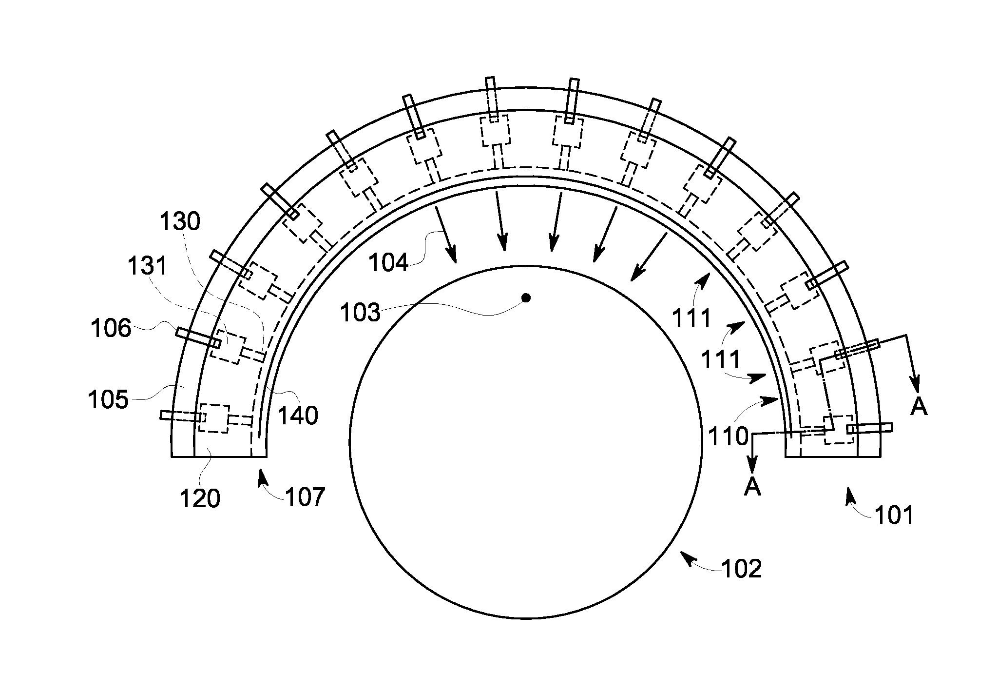
[0016]FIG. 1 illustrates a high frequency ultrasonic probe 101 being used to inspect test object 102, which can be, for example, a bar or billet, in order to detect a small flaw 103 in the material of the test object. The ultrasonic probe 101, formed in a predetermined curved shape, or contour, in this embodiment, comprises ultrasonic transducers 111 on an active surface 110 of the ultrasonic probe 101 which direct ultrasonic energy 104 toward the test object 102. A subset of the ultrasonic transducers 111 is typically activated at one time to emit ultrasonic energy 104 toward a test object. A portion of the ultrasonic transducer electrodes 130 extend from the active surface 110 of the ultrasonic probe 101 onto a side surface (the side facing the viewer in FIG. 1) of the ultrasonic probe 101. Another portion of the ultrasonic transducer electrodes 130 extend from the active surface 110 of the ultrasonic probe 101 onto an opposite side surface (the side opposite, and not visible to, ...


PUM


Abstract

An array of ultrasonic transducers is formed on a piezoelectric polymer foil. Ultrasonic transducer electrodes are formed on a first side of the foil and a ground layer is formed on a second side of the foil.

Description

BACKGROUND OF THE INVENTION[0001]The subject matter disclosed herein relates to an ultrasonic probe and, in particular, to a probe operable at high ultrasonic frequencies.[0002]Nondestructive testing devices can be used to inspect test objects to detect and analyze anomalies in the objects. Nondestructive testing allows an inspection technician to maneuver a probe near the surface of the test object in order to perform testing of both the object surface and its underlying structure. One example of nondestructive testing is ultrasonic testing.[0003]In an ultrasonic testing system, electrical pulses are transmitted to an ultrasonic probe where they are transformed into ultrasonic pulses by one or more ultrasonic transducers (e.g., piezoelectric elements) in the ultrasonic probe. During operation, the electrical pulses are applied to the electrodes of one or more ultrasonic transducers, generating ultrasonic waves that are transmitted into the test object to which the probe is coupled....

Claims


Application Information

Patent Timeline
Patent Type & Authority Applications(United States)
IPC IPC(8): B06B1/06H01L41/053
CPCB06B1/0692G01N29/2487G01N2291/106
Inventor OBERDOERFER, YORK
Owner GENERAL ELECTRIC CO
Why Eureka
Try Eureka