System and method for configuring a logic analyzer to trigger on data communications packets and protocols

a logic analyzer and data communication technology, applied in the field of logic analyzers, can solve the problems of difficult and inconvenient learning of such a programming language, requiring considerable time and effort to formulate even simple trigger definitions, and constructing trigger definitions can be very complicated and time-consuming

Inactive Publication Date: 2005-02-01
AGILENT TECH INC
View PDF13 Cites 55 Cited by
  • Summary
  • Abstract
  • Description
  • Claims
  • Application Information

AI Technical Summary

Benefits of technology

Various embodiments of the present invention provide certain advantages and overcome certain drawbacks of the conventional techniques. Not all embodiments of the invention share the same advantages and those that do may not share them under all circumstances. Further features and advan

Problems solved by technology

Inside the switching systems, a commercial network or protocol analyzer is of no use, as the protocols used internally are often non-standard, and the buses cannot be connected to the network interfaces of protocol analyzers.
Constructing a trigger definition can be very complicated and time consuming.
Learning such a programming language is often difficult and inconvenient.
However, even with such proficiency and knowledge, formulation of even simple trigger definitions still requires considerable time and effort due to the complexity of the programming language.
In other words, such programming languages, although suited for development of complicated trigger definitions, are burdensome to developing simple and complicated trigger definitions alike.
Logic analyzers provide many configuration functions as a result of the increasing operational complexity of target devices.
Als

Method used


Image

  • System and method for configuring a logic analyzer to trigger on data communications packets and protocols
  • System and method for configuring a logic analyzer to trigger on data communications packets and protocols
  • System and method for configuring a logic analyzer to trigger on data communications packets and protocols

Examples


Embodiment Construction

The present invention is directed to signal measurement systems that acquire and store signal data in accordance with a trigger specification. The present invention is a system and method for configuring a signal measurement system, such as a logic analyzer, to trigger on data communications packets and constructs within selected protocols. That is, the present invention presents a system and method that simplifies constructing trigger definitions for logic analyzers. Further, the present invention provides a graphical user interface whereby a user can construct said trigger definitions. Specifically, the present invention displays an event editor graphical user interface enabling construction of trigger definitions through use of protocol definitions stored in memory.

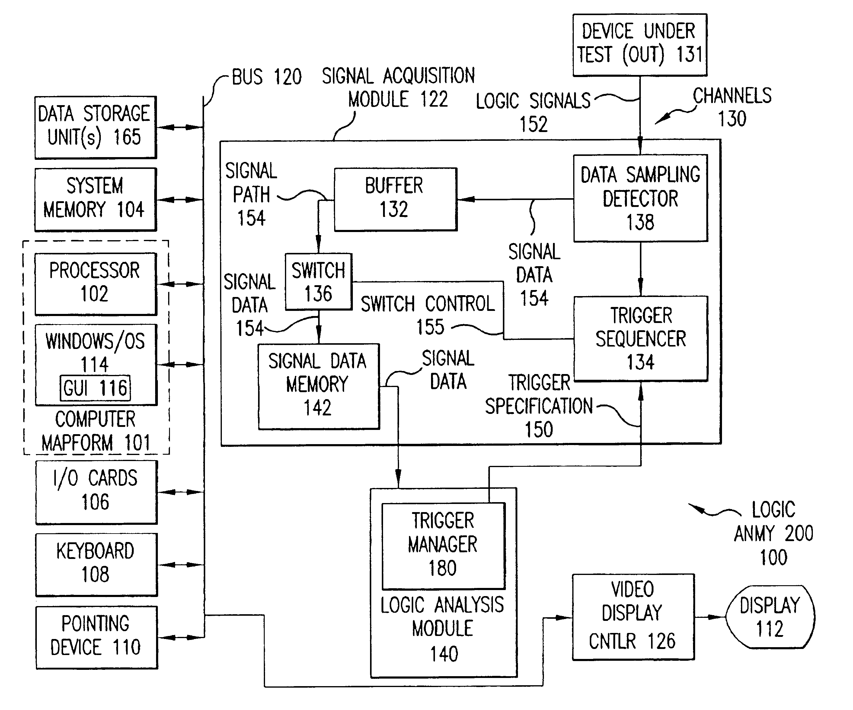
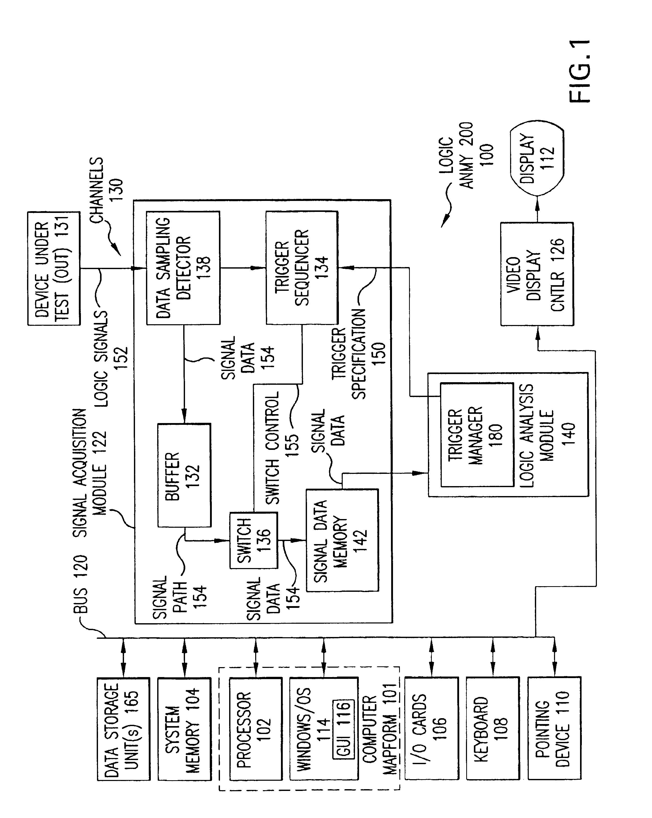
FIG. 1 is a functional block diagram of a typical logic analyzer. Logic analyzer 100 acquires, analyzes and displays a wide variety of signals generally in terms of the logic level of the signals versus time. In the il...


PUM


Abstract

A trigger function display system and methodology for trigger definition development in a signal measurement system having a graphical user interface. The system displays a plurality of graphically selectable icons and an associated protocol profile window. The protocol profile window includes at least a protocol descriptor field and a protocol editors field. The user inputs data into the protocol editors field which causes the system to automatically construct a bit sequence utilizing a plurality of event definitions stored in memory. The event definitions are two bit blocks resulting from the parsing of protocol definition text files. The bit sequence is used to then construct a series of trigger primitives. An optimizing routine is used to consolidate consecutive multiple occurrences of identical bit patterns in the bit sequence into single trigger primitives.

Description

FIELD OF THE INVENTIONThe present invention relates generally to logic analyzers used in measurement of data in digital data switching systems, such as routers, switches and hubs that carry communication data on parallel buses, and more particularly to the construction of trigger sequences allowing a logic analyzer to trigger on data communications packets and constructs within selected protocols.BACKGROUND OF THE INVENTIONAs known by those skilled in the art, a logic analyzer is an electronic instrument used to detect, analyze, and display digital signals. Logic analyzers are commonly used to debug the internal operation of digital data switching systems such as routers, switches, and hubs. These digital data switching systems carry communication data on parallel buses. Inside the switching systems, a commercial network or protocol analyzer is of no use, as the protocols used internally are often non-standard, and the buses cannot be connected to the network interfaces of protocol ...

Claims


Application Information

Patent Timeline
IPC IPC(8): G09G5/00G06F11/25H04L12/26H04L29/06
CPCG06F11/25H04L12/2697H04L43/50H04L69/22H04L43/18Y10S715/969
Inventor FERGUSON, SCOTT ROJENNES, DANIEL JAMES
Owner AGILENT TECH INC
Why Eureka
Try Eureka