Variable use fly-fishing reel

a fly-fishing reel and variable-use technology, applied in fishing, motor/generator/converter stopper, dynamo-electric converter control, etc., can solve the problem of binding between the spool and the spindle, and achieve the effect of convenient switching, greater mechanical advantage, and greater length of lin

Inactive Publication Date: 2005-02-08
GILMORE DAVID F
View PDF24 Cites 26 Cited by
  • Summary
  • Abstract
  • Description
  • Claims
  • Application Information

AI Technical Summary

Benefits of technology

When the reel is designed to allow switching between left- and right-handed operation without requiring the rewinding of the line on the spool, additional elements are required. For such operation, the pawl assembly is a bi-positional assembly which allows selectively positioning the pawl assembly with respect to the base plate between a first pawl assembly position, where the pawl assembly allows rotation of the spindle shaft in the first direction but prevents rotation of the spindle shaft in the second and opposite direction, and a second pawl assembly position, which allows rotation of the spindle shaft in the second direction while preventing rotation in the first direction.
When the spool is to be reversible, a spool second end friction surface is provided, which surrounds the spool central passage at the spool second end. The spool second end friction surface can be engaged with the flange friction washer in place of the spool first end friction surface. Again, it is preferred to employ a separate friction disk and, in this case, the sleeve is configured to reside in the spool central passage and extend to the friction disks, preferably being retained thereby. It is also preferred for the friction disks to be fabricated from sheet stock and configured to grippably engage the spool first end and the spool second end. Also provided are means for lockably engaging the spool-engaging side with the spool first end. When recesses on the spool second end are employed, identical recesses can be employed on the spool first end. With these additional changes, the reel can be readily reversed on the spindle shaft to convert the reel from a left-handed mode of operation to a right-handed mode without requiring the line to be rewound onto the spool.
Independently of whether the spool is reversible, supplemental spools can be provided which are configured to slidably and rotatably engage the spindle shaft and lockably engage the drive plate in place of the original spool. These supplemental spools allow a user to readily switch between different weights of fishing lines and / or to switch between a small arbor spool, allowing a greater length of line to be carried, and a large arbor spool, allowing greater mechanical advantage when retrieving the line.

Problems solved by technology

However, many of the self-lubricating materials suitable for this purpose tend to swell when immersed in salt water, and thus can cause binding between the spool and the spindle.

Method used


Image

  • Variable use fly-fishing reel
  • Variable use fly-fishing reel
  • Variable use fly-fishing reel

Examples


Embodiment Construction

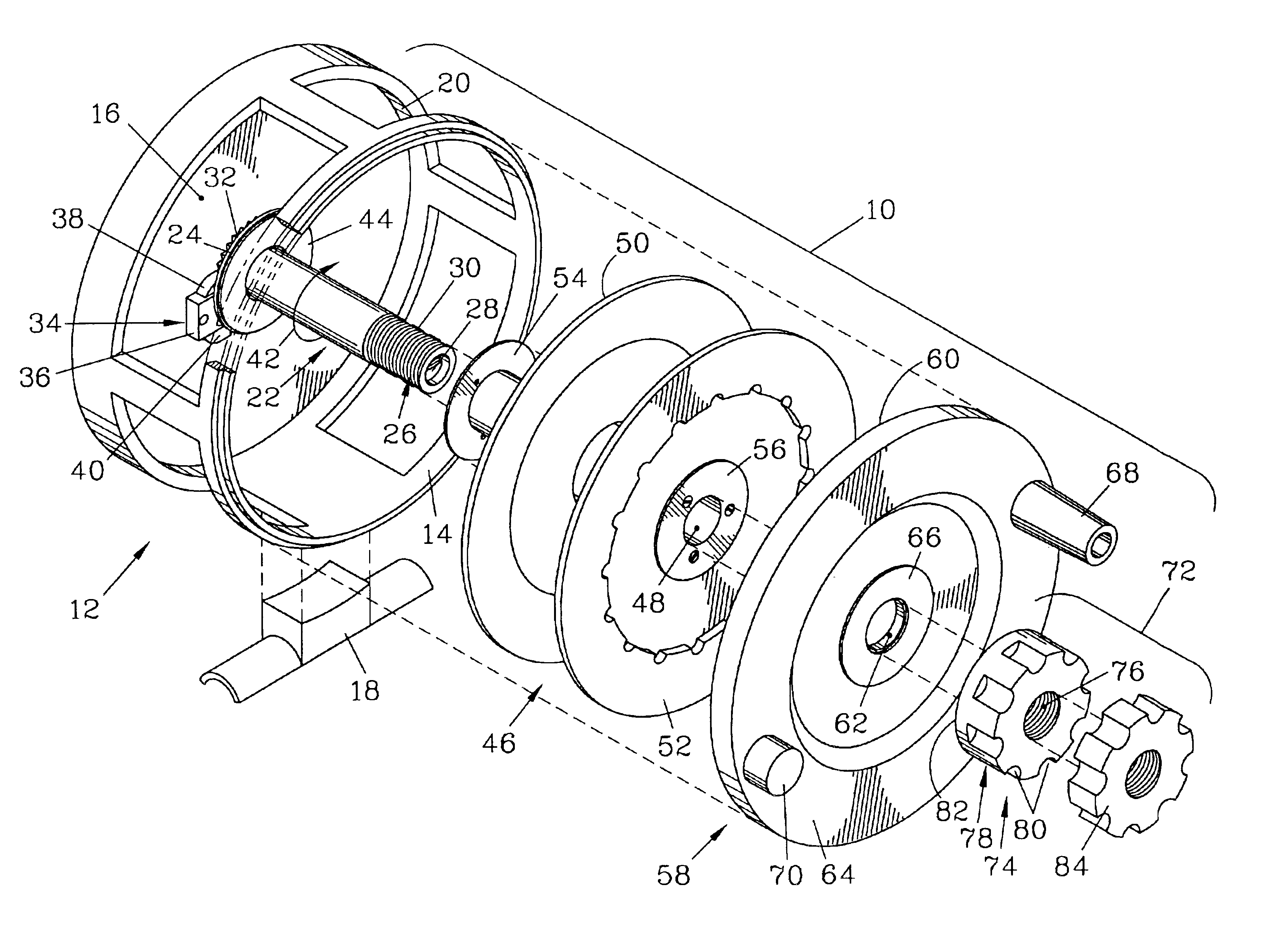
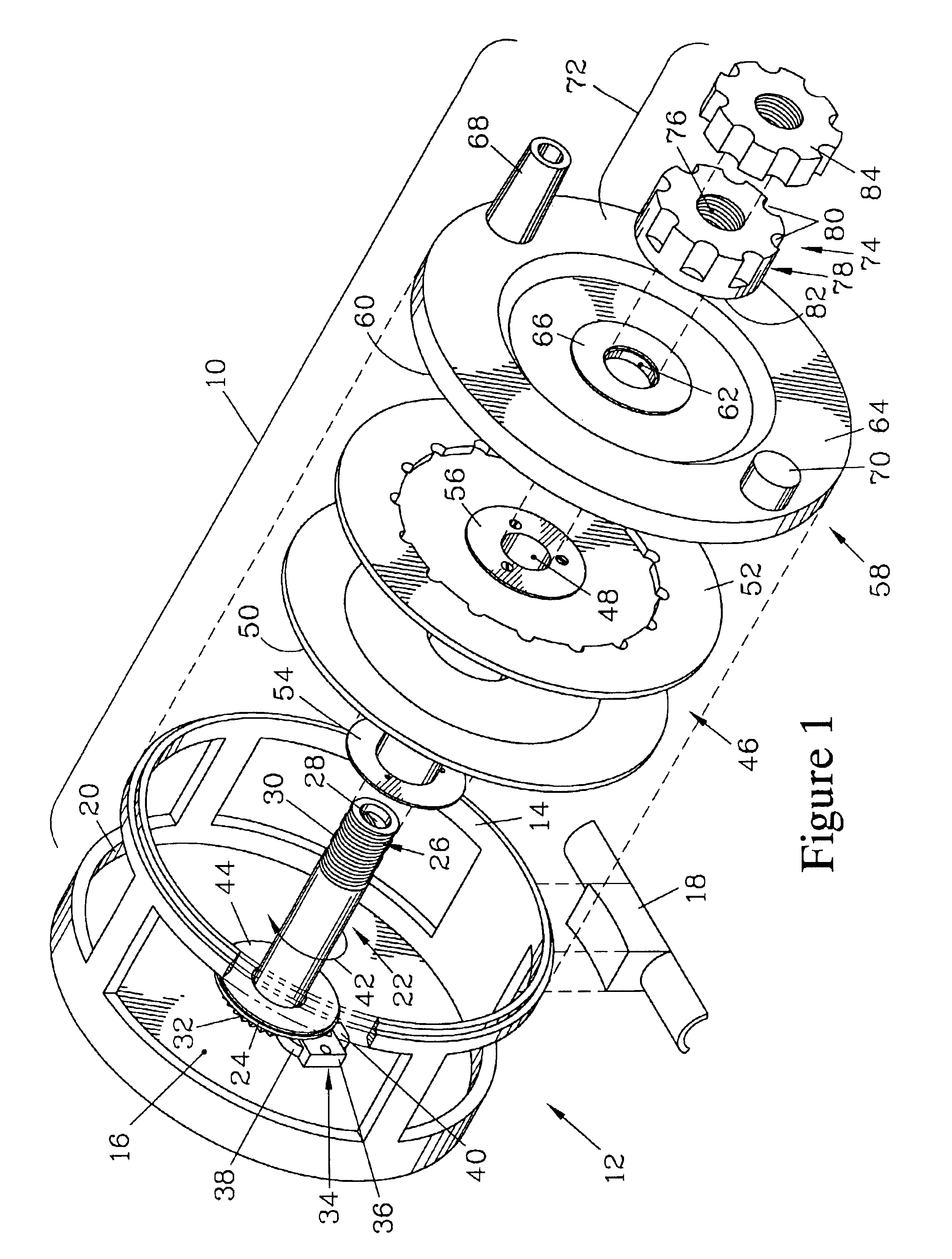
FIG. 1 is an exploded isometric view of a fly-fishing reel 10 of the present invention. A reel body 12 is provided, which in the illustrated embodiment has a full cage case having a rim 14 that forms a complete circle. The reel body 12 has a base plate 16 that forms the back of the fly-fishing reel 10. The fly-fishing reel 10 is designed to be quickly and simply configured to be used either as a left-handed reel or as a right-handed reel.

The reel body 12 is mountable on a fishing pole (not shown) by a reel mount 18 attaching to the reel body 12. A reel arbor (not shown) is centrally mounted on the base plate 16 and extends therefrom. The base plate 16 is bounded by an annular wall 20, which is symmetrically disposed about the reel arbor.

A spindle shaft 22 that terminates in a spindle flange 24 and a free end 26 rotatably engages the reel arbor and is secured thereto by a screw 28 or similar fastener. The free end 26 of the spindle shaft 22 has a threaded portion 30. A gear 32 is fix...


PUM


Abstract

A fly-fishing reel has a reel body with a reversible pawl and an arbor. A spindle shaft with a gear rotates on the arbor, the gear and pawl limiting the direction of rotation. A spool and lockably engaged drive plate rotate on the spindle shaft and are secured thereon by a drag capsule which attaches to the spindle shaft. Tightening the drag capsule on the spindle shaft forcibly engages friction surfaces on the spindle shaft, the spool, the drive plate, and the drag capsule to provide an adjustable dual disk drag mechanism, as well as securing the drive plate and spool together. The spool can be readily replaced with a different spool and the spools are preferably reversible on the spindle shaft. A winding handle is attached to the drive plate to provide direct-drive action, or is attached to the drag capsule to provide a non-return action.

Description

FIELD OF THE INVENTIONThe present invention is for a fishing reel suitable for fly-fishing, and more specifically for a fishing reel which allows an operator to readily change spools while providing a double disk drag action for smoother operation. The fishing reel of the present invention can preferably also allow a user to change the operating characteristics of the reel to suit various applications.BACKGROUND OF THE INVENTIONFishing reels attach to a fishing pole and serve to handle a fishing line which is wound onto a spool of the reel. The reel allows the user to wind line onto the spool to retrieve the line after it has been cast and to bring in a fish hooked to the line, and allows a fish hooked onto the line to “run” with the line, in which the fish unwinds line from the reel under a frictional drag force which tires the fish. In fly-fishing, presentation of the baited hook attached to the line is critical, and thus the weight of the line must be properly suited to the condi...

Claims


Application Information

Patent Timeline
Patent Type & Authority Patents(United States)
IPC IPC(8): A01K89/016A01K89/00
CPCA01K89/016A01K89/004A01K89/0155A01K89/0162A01K89/0179A01K89/01931A01K89/058
Inventor GILMORE, DAVID F.
Owner GILMORE DAVID F
Why Eureka
Try Eureka