Electric fan assembly and fan assembly method

a technology of electric fans and fan assemblies, which is applied in the field of self-standing electric fans, can solve the problems of presenting a trip hazard, the self-standing fans have had certain pronounced problems, and the packaging, shipping, and selling of these fans in a fully assembled configuration is not practicabl

Inactive Publication Date: 2005-02-08
HUNTER FAN
View PDF7 Cites 12 Cited by
  • Summary
  • Abstract
  • Description
  • Claims
  • Application Information

AI Technical Summary

Problems solved by technology

Due to their length, especially those whose height is fixed, it is impractical to package, ship, store and sell these fans in a fully assembled configuration.
The just described multi-unit, self standing fans have had certain pronounced problems.
Not only has it been visually displeasing, but it has presente...

Method used


Image

  • Electric fan assembly and fan assembly method
  • Electric fan assembly and fan assembly method
  • Electric fan assembly and fan assembly method

Examples


Embodiment Construction

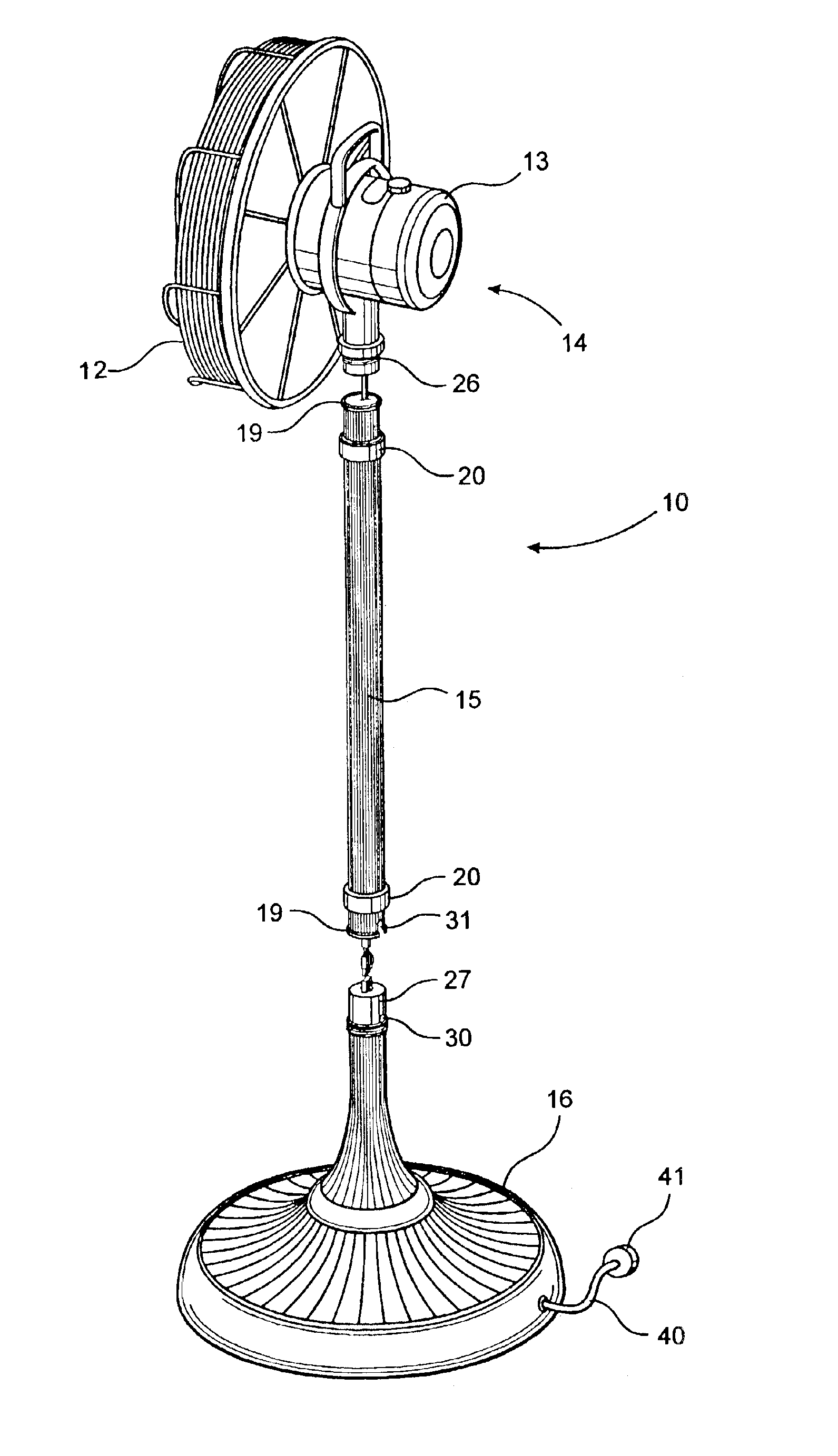
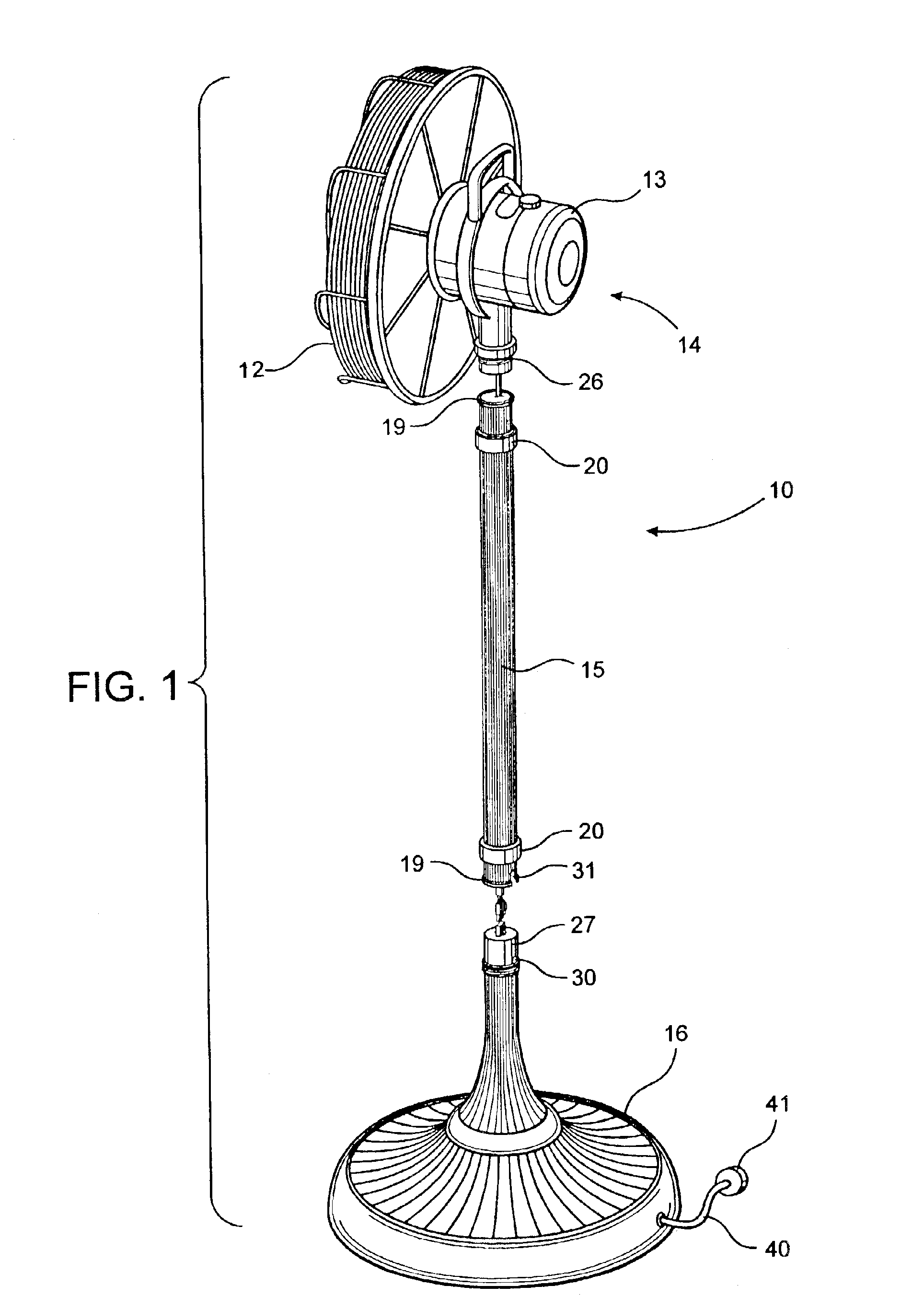
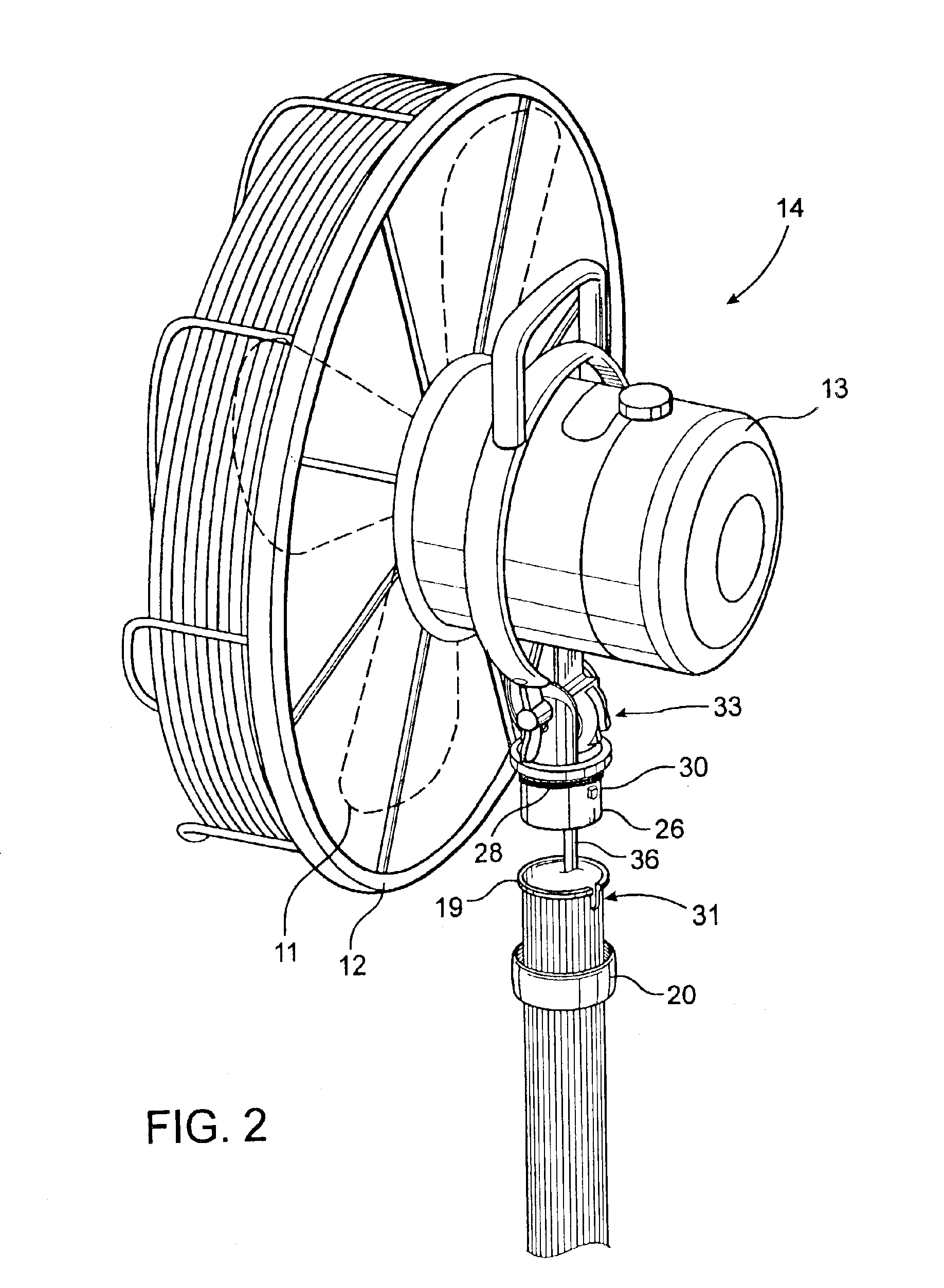
With reference now in more detail to the drawing there is shown an electric fan assembly 10 that has a set of fan blades 11 mounted within a protective grill 12 that are rotatably driven by an electric motor shown generally at 13 in a conventional manner. Preferably the fan blade and motor module 14 is oscillatory although it need not be. The module is supported above a floor or the like by a decorative hollow, cylindrical shaft or pole 15 and base or stand 16. As best shown in FIG. 1, the fan assembly can be configured in a broken down configuration for packaging, shipping and storage into its three distinct units, namely its motor driven blades module 14, its shaft 15 and its base 16. For use it is easily reconfigured into an assembled configuration as hereafter described.

The shaft 15 is packaged with two mounting collars or rings 20 slidably mounted on the shaft. These are mounted trapped or captured between end flanges 19 of the shaft 15 so that they cannot come off the shaft. A...


PUM


Abstract

An electric fan assembly has structurally independent motor driven blades module, stand and shaft. The module and stand are mechanically assembled together by two mounting rings that are captured on the shaft. Electrical connections are also made during mechanical assembly with mateable connectors on internal cords.

Description

TECHNICAL FIELDThis invention relates generally to electric fans, and more specifically to self standing electric fans that are packaged and sold in multiple units for later assembly.BACKGROUND OF THE INVENTIONSelf standing electric fans usually have motor driven fan blades mounted atop a pole or shaft that extends uprightly from a base or stand. Most of these have the motor driven fan blades constructed as a module that oscillates to distribute their air flow. Some have the module mounted to the shaft about four feet above the floor. Others have telescoping shafts so that the height of the blades module may be varied. Due to their length, especially those whose height is fixed, it is impractical to package, ship, store and sell these fans in a fully assembled configuration. Accordingly, they have often been designed, packaged and distributed in a broken-down configuration.Heretofore, such self standing fans have been segmented for packaging into three discrete units, namely into a ...

Claims


Application Information

Patent Timeline
IPC IPC(8): F04D29/60
CPCF04D29/601
Inventor CORTEZ, EDWARD E.
Owner HUNTER FAN
Why Eureka
Try Eureka