
Method and apparatus for calibrating voltage-controlled devices

Inactive Publication Date: 2005-02-08
QUALCOMM INC
View PDF15 Cites 29 Cited by
  • Summary
  • Abstract
  • Description
  • Claims
  • Application Information

AI Technical Summary

Benefits of technology

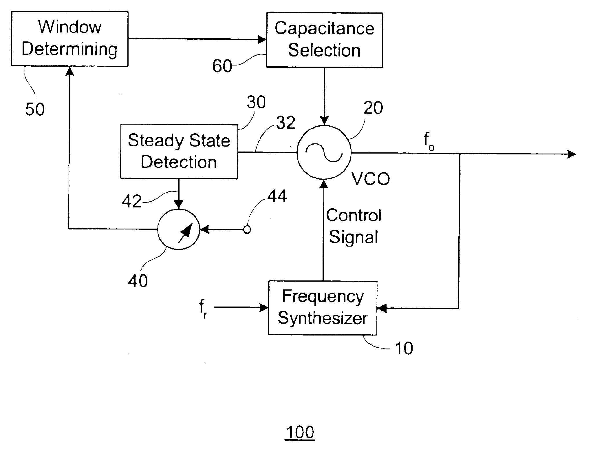
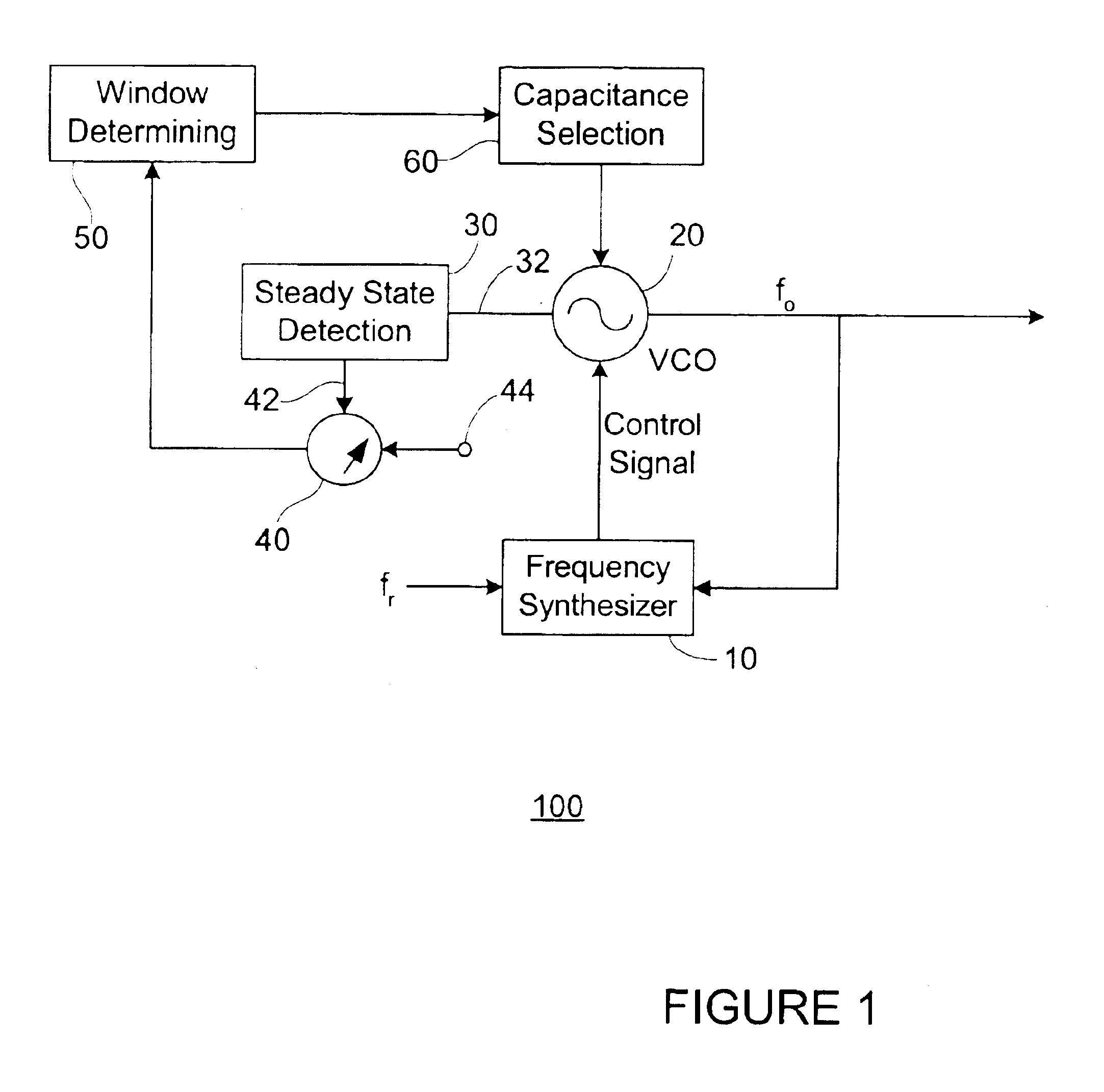
In a first exemplary embodiment, the present invention maintains a control voltage within a predetermined tuning sensitivity window or tuning sensitivity range, and thus the output frequency can be rapidly and accurately controlled. In a second exemplary embodiment, the present inventive method and apparatus calibrates a PLL that includes multiple VCOs. In a third exemplary embodiment, the present invention calibrates control voltages to compensate for changes in temperature.

Problems solved by technology

Disadvantageously, voltage-controlled circuit elements having wide tuning ranges are extremely sensitive to small changes in the control voltage (i.e., small changes in the control voltage result in large changes in output frequency), which is undesirable in practical circuit applications such as VCOs.
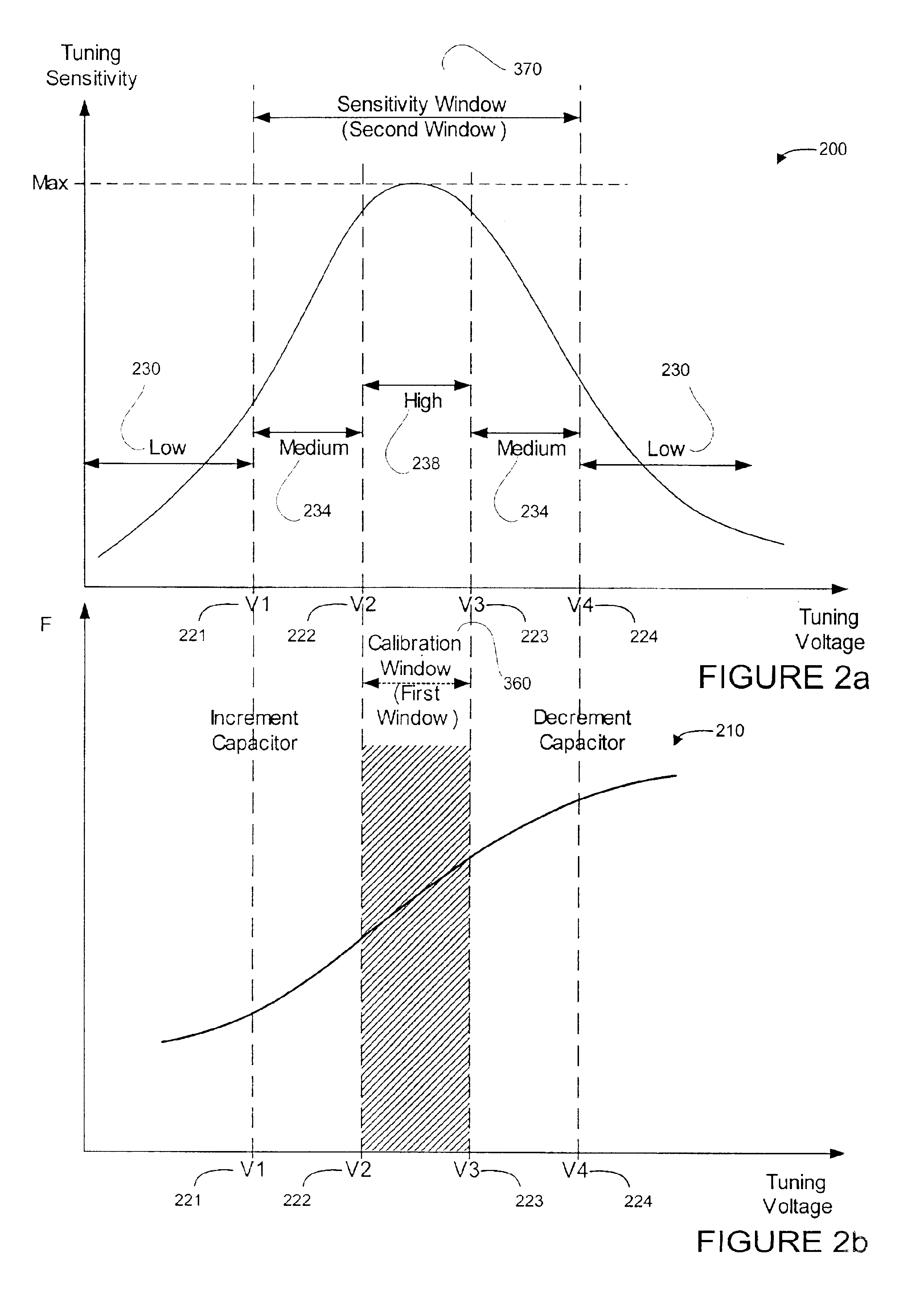
One drawback of the coarse / fine tuning method is that the varactors used to implement the method are non-linear by nature, and thus tuning sensitivity (i.e., the ability to change capacitance or capacitance-related characteristics in accordance with a control voltage) varies greatly depending upon the control voltage.
Thus, an application that implements the coarse / fine tune method may attempt to operate in a low sensitivity tuning range, which can limit its overall operating frequency range.
Another drawback associated with the coarse / fine tune method is the lack of a means for calibrating control voltage drift due to temperature variations.
For example, circuit temperature can increase during circuit operation from morning to afternoon; and temperature-dependent circuit characteristics can cause the control voltage to drift into tuning regions having low sensitivity.
Thus, the frequency range of the PLL may be limited by the temperature variations.
Accordingly, the effective operating temperature range of the circuit is limited without calibration.

Method used


Image

  • Method and apparatus for calibrating voltage-controlled devices
  • Method and apparatus for calibrating voltage-controlled devices
  • Method and apparatus for calibrating voltage-controlled devices

Examples


Embodiment Construction

Throughout this description, the preferred embodiment and examples shown should be considered as exemplars, rather than as limitations on the present invention.

The present invention is a method and apparatus for calibrating a voltage-controlled device in a control loop. The present invention maintains a control voltage of a voltage-controlled device within a high tuning sensitivity range, and thus improves circuit performance. The present inventive method and apparatus features a voltage “windowing” or ranging method wherein a high tuning sensitivity window (i.e., range) is a subset of a low tuning sensitivity window.

Several exemplary embodiments of the present invention are described. In a first exemplary embodiment, the present invention maintains a control voltage within a predetermined tuning sensitivity window or tuning sensitivity range. In a second exemplary embodiment, the present inventive method and apparatus calibrates a PLL that includes multiple VCOs. In a third exempla...


PUM


Abstract

A method and apparatus for calibrating a voltage-controlled device in a control loop is disclosed. The method and apparatus of the present invention maintains a control voltage of a voltage-controlled device within a high tuning sensitivity range, and thus improves the performance of the voltage-controlled device. The present inventive method and apparatus features a voltage windowing method wherein a high tuning sensitivity window is a subset of the low tuning sensitivity window. In one embodiment, the present invention maintains a control voltage within a predetermined tuning sensitivity window or range. In another embodiment, the present inventive method and apparatus calibrates a PLL that includes multiple VCOs. In yet another embodiment, the present invention calibrates control voltages to account for changes in operating temperature.

Description

BACKGROUND OF THE INVENTION1. Field of the InventionThis invention relates to integrated circuit devices, and more particularly to a method and apparatus for calibrating voltage-controlled devices in control loop circuits.2. Description of Related ArtVoltage-controlled devices used as basic building blocks in a variety of practical applications. For example, transmitters typically include voltage-controlled oscillators (VCO) that operate over a wide frequency range. These VCOs include voltage-controlled circuit elements such as variable capacitors (i.e., varactors) that have wide tuning ranges.Disadvantageously, voltage-controlled circuit elements having wide tuning ranges are extremely sensitive to small changes in the control voltage (i.e., small changes in the control voltage result in large changes in output frequency), which is undesirable in practical circuit applications such as VCOs.One method of implementing a VCO that attempts to overcome the above described sensitivity pr...

Claims


Application Information

Patent Timeline
IPC IPC(8): H03B5/08H03B5/12H03L7/099H03L7/10
CPCH03L7/099H03L7/10H03B5/1293H03B5/1215H03B5/1243H03B5/1265H03B5/1231H03L2207/06H03L7/102
Inventor LING, CURTIS CHIH-SHAN
Owner QUALCOMM INC
Learn More