
Temperature control for conductive member

a technology of conductive components and temperature control, which is applied in the direction of resistance/reactance/impedence, instruments, heat measurement, etc., can solve the problems of delay in thermal sensing, difficult to sense and control the temperature correctly, and difficult rapid temperature sensing

Inactive Publication Date: 2003-12-09
NAGOYA INSTITUTE OF TECHNOLOGY
View PDF8 Cites 1 Cited by
  • Summary
  • Abstract
  • Description
  • Claims
  • Application Information

AI Technical Summary

Benefits of technology

As the pulse current with the predetermined pulse is applied to the conductive member at the predetermined interval, unnecessary heating is avoided. Thus, as a heavy-current can be applied to the conductive member, it is possible to detect extremely small electric resistance at the order of 10.sup.-4 .OMEGA.. Also, when the current is applied to the conductive member at the predetermined, e. g. a relatively short time interval, the voltage of the conductive member can be always detected while the pulse current is applied. Therefore, it is possible to control the temperature of the conductive member following the rapid temperature change. As a result, more accurate temperature control can be performed.
By such cooling and / or heating, it is possible to cool and / or heat the conductive member rapidly, and thus it is possible to control the temperature of the conductive member rapidly.
With the above-mentioned element according to the invention, it is possible to control the trap tube accurately and rapidly, and thus a separation of trapped sample gas into components consisting of the sample gas can be performed at high accuracy.
In view of the foregoing, it is an object of the present invention to provide a device for controlling the temperature of the conductive member, e. g. a trap tube consisting of a conductive material correctly and rapidly.

Problems solved by technology

As a result, it is difficult to sense and control the temperature correctly.
Rapid temperature sensing is often difficult because of the comparatively large heat capacity of the temperature sensor itself and its fixture, and thus there is a delay in the thermal sensing.
Such a delay is significant if the thermistor is jointed to the tube directly because the heat capacity at the joint of the thermistor and the tube becomes large.
As a result, it is difficult to sense and control the temperature rapidly.

Method used


Image

  • Temperature control for conductive member
  • Temperature control for conductive member
  • Temperature control for conductive member

Examples


Embodiment Construction

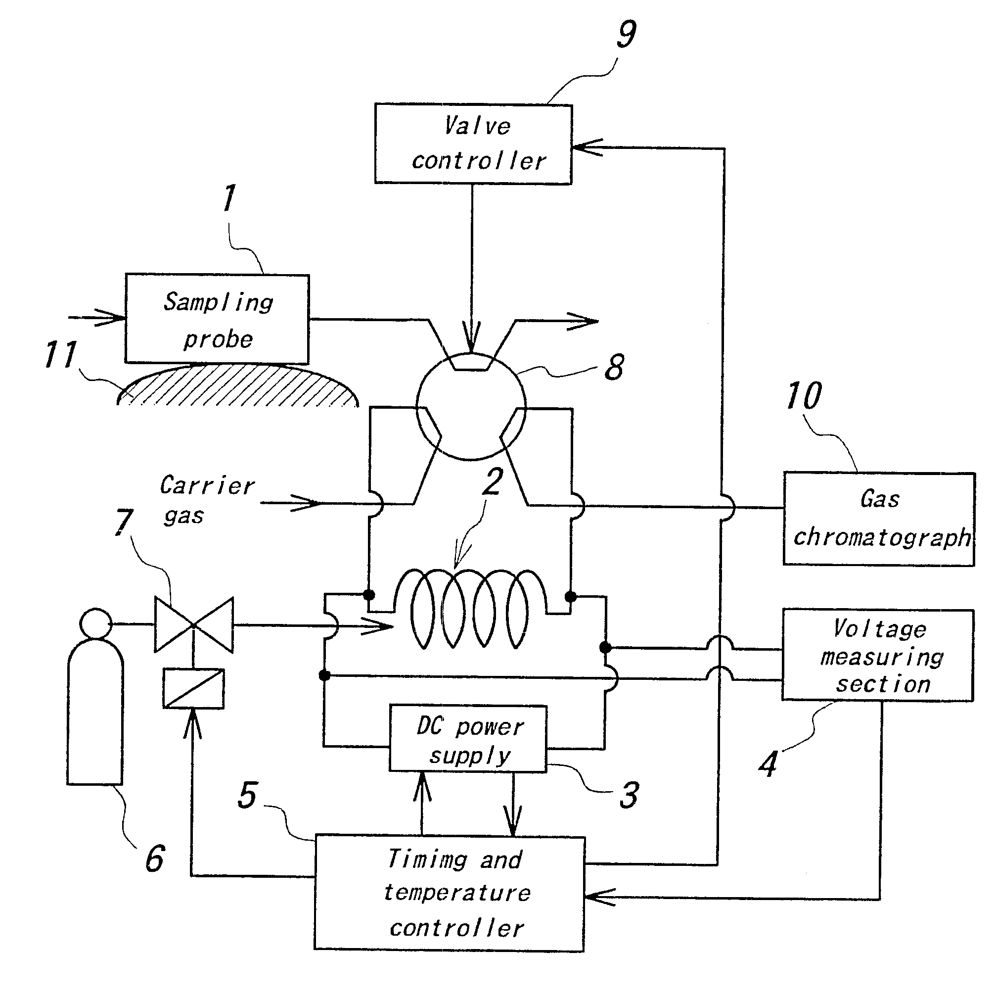
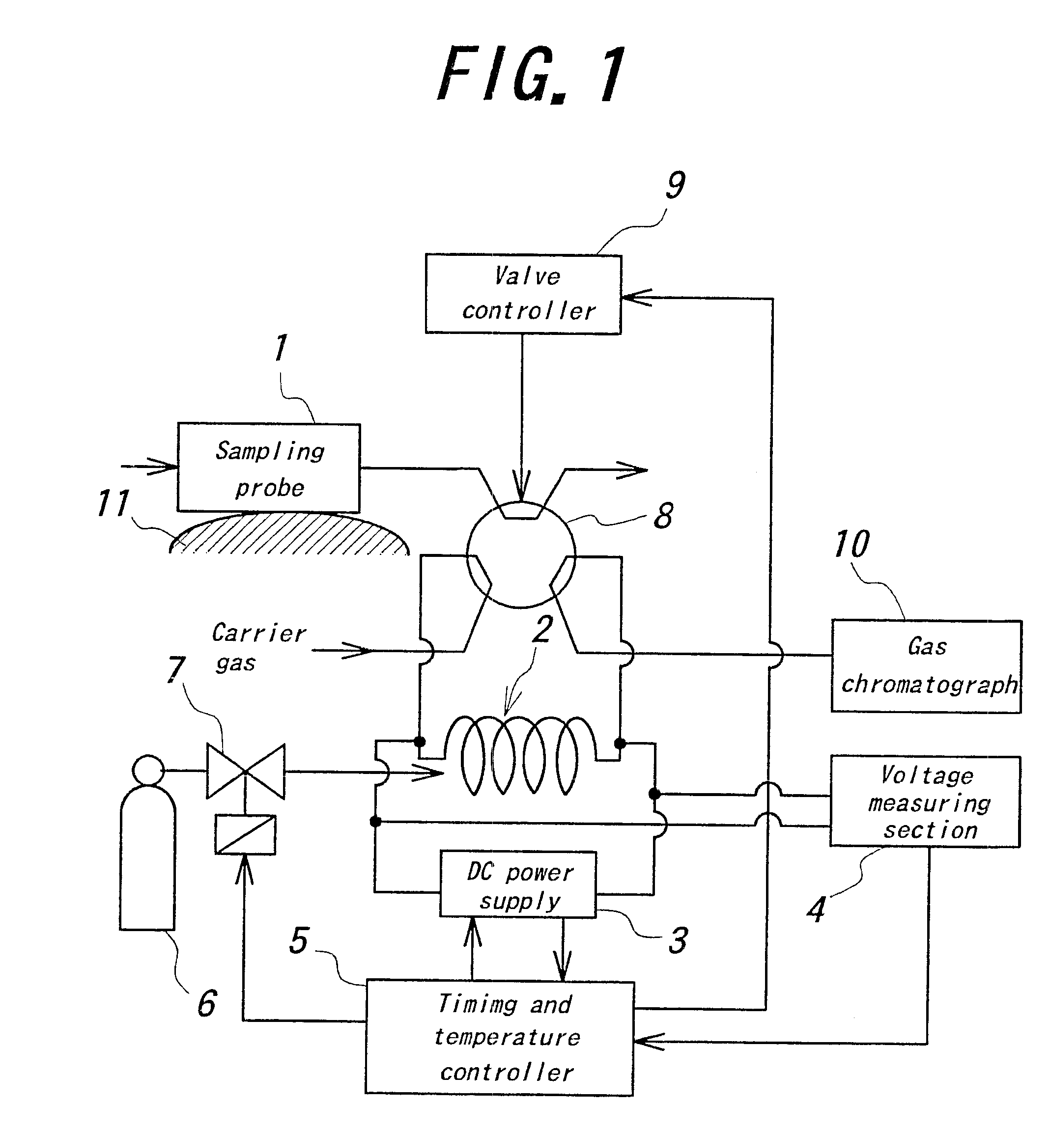
FIG. 1 is a schematic diagram showing embodiment of the device for controlling the temperature of the conductive member according to the present invention. In the embodiment, the device is applied to the trapping system for gas chromatograph and comprises a sampling probe 1, a metal trap tube 2, DC power supply 3, a voltage measuring section 4, a timing and temperature controller 5, a liquid carbon dioxide cylinder 6, solenoid valve 7, a six-way valve 8, a valve controller 9, and a gas chromatograph 10.

The sampling probe 1 for sample gas presents above a skin 11 of human continuously. A nitrogen gas system is passed through the sampling probe 1. The sample gas involved in the nitrogen gas stream is led into the trap tube 2. The trap tube 2 collects gas sampled by the sampling probe 1.

The DC power supply 3 applies a dc pulse to detect the temperature of the trap tube 2. The DC power supply 3 also supply the direct electric current to the trap tube 2, or apply the pulse current to the...


PUM

PropertyMeasurementUnit
electrical resistanceaaaaaaaaaa
electric resistanceaaaaaaaaaa
internal diameteraaaaaaaaaa

Abstract

A device for controlling the temperature of a conductive member, which detects the electrical resistance of the conductive member, calculates the temperature of the conductive member based on the detected electric resistance, and adjusts the temperature of the conductive member based on the calculated temperature, is disclosed.

Description

1. Field of the InventionThe present invention relates generally to a device for controlling the temperature of a conductive member, and to a gas chromatography system incorporating such a device.2. Description of the Related ArtTemperature control is widely performed in many fields, such as gas chromatography. In gas sample chromatography, a system typically includes a section for cooling and collecting gas. The section collects rarefied sample gas in a trap tube by concentrating the sample gas, conveys the gas into a column at a relatively narrow zone, and separates the sample gas into its components. Such a gas chromatography system is widely used in the field of analysis or measurement of gas. It is desirable to collect sample gas in the trap tube and convey the trapped sample gas into the column accurately and rapidly. In order to accomplish this, accurate and rapid sensing and control of the temperature at the trap tube is required.The trapping system for gas chromatograph con...

Claims


Application Information

Patent Timeline
Patent Type & Authority Patents(United States)
IPC IPC(8): G01N30/00G01N30/30G01N30/12G01K7/18G01N1/22G01N1/28G01N30/08
CPCG01N30/30G01N2030/3069G01N2030/3061G01N2030/121
Inventor TSUDA, TAKAONAITO, KEN
Owner NAGOYA INSTITUTE OF TECHNOLOGY
Learn More