Mops and mop components

a technology of mop components and mop blades, which is applied in the field of mop blades, can solve the problems of reducing affecting the service life of the mop blade, and requiring substantial physical effort to compress the absorbent member, so as to achieve quick and easy removal and easy replacement.

Inactive Publication Date: 2005-02-15
FREUDENBERG HOUSEHOLD PROD LP
View PDF17 Cites 11 Cited by
  • Summary
  • Abstract
  • Description
  • Claims
  • Application Information

AI Technical Summary

Benefits of technology

In accordance with a highly preferred embodiment of the invention, the mop element includes a compressible liquid absorbent outer layer and a flexible, relatively tough inner layer adapted to overlie the mop element support. The wings of the support are provided with apertures which align respectively with apertures in the inner layer of the mop element. Fasteners are used to maintain the inner layer against the support. Most preferably, the fasteners comprise a rivet portion having an apertured head and a longitudinally slotted outer sleeve, and an inner pin portion having a headed end and an operative end opposite thereof. By introducing the headed end of the pin portion into the slot of the rivet portion, the pin engages and enlarges the outer sleeve to removably retain the inner layer and wing together. By so attaching the mop element to the mop element support, the mop element may be quickly and easily removed when spent, and may be readily replaced with a fresh mop element. The mop element may be provided with plural apertures sized to fit a variety of mop element supports.

Problems solved by technology

A common problem with conventional butterfly mops is the difficulty inherent in manually applying sufficient force to the actuating mechanism to fold the liquid absorbent member over onto itself and to compress the liquid absorbent member sufficiently to satisfactorily expel liquid therefrom.
Indeed, in typical butterfly mops, substantial physical effort may be required to compress the absorbent member.
Another drawback lies in the difficulty of removing a spent liquid absorbent member and of attaching a new liquid absorbent member.
A liquid absorbent member from one mop often will not fit on a second mop, and thus retailers must stock many different sizes of mop elements.

Method used


Image

  • Mops and mop components
  • Mops and mop components
  • Mops and mop components

Examples


Embodiment Construction

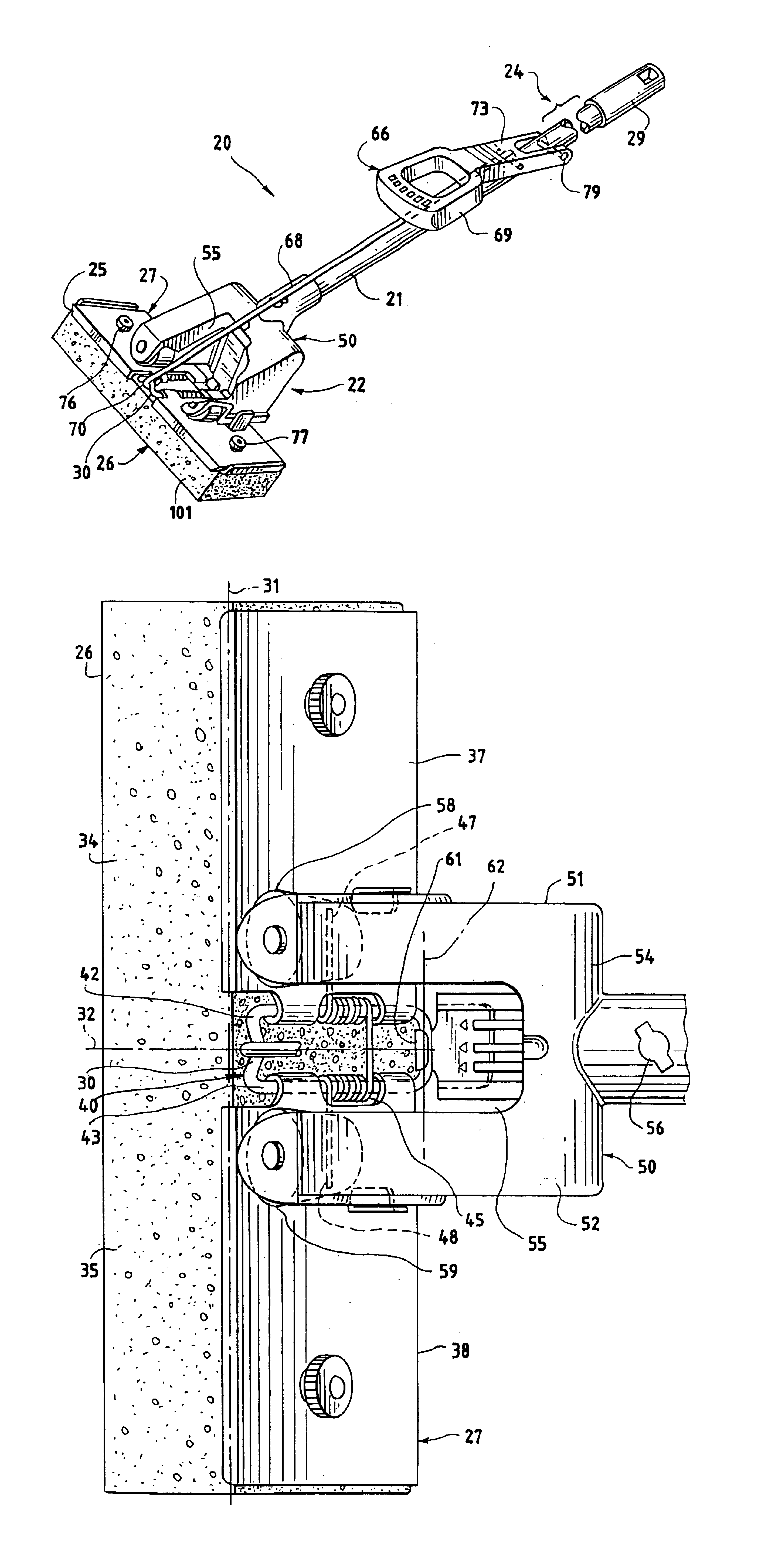
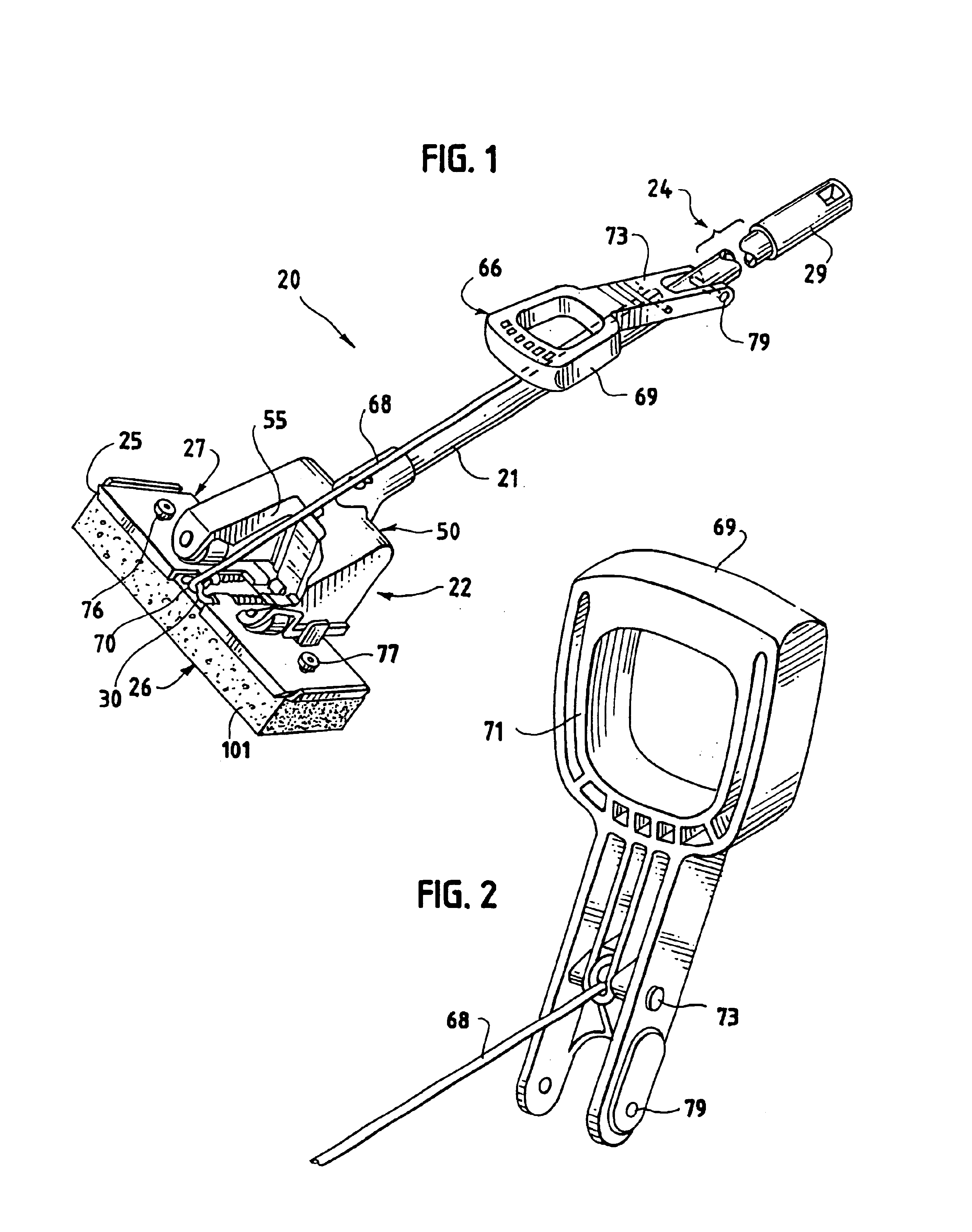
Referring now to FIGS. 1-4, the butterfly mop 20 generally includes a mop shaft 21 having a mopping end 22 and a gripping end 24. Disposed at the mopping end 22 is a mop element assembly 25 including a mop element 26 and a mop element support 27. The mop element 26 includes an absorbent member of spongy material as shown in FIG. 1 and a flexible, relatively tough inner layer (not shown in FIG. 1) which is secured to the support 27, by fasteners 76, 77. At the gripping end 24 of the mop shaft 21 is disposed a hanger clip 29 for supporting the mop for storage.

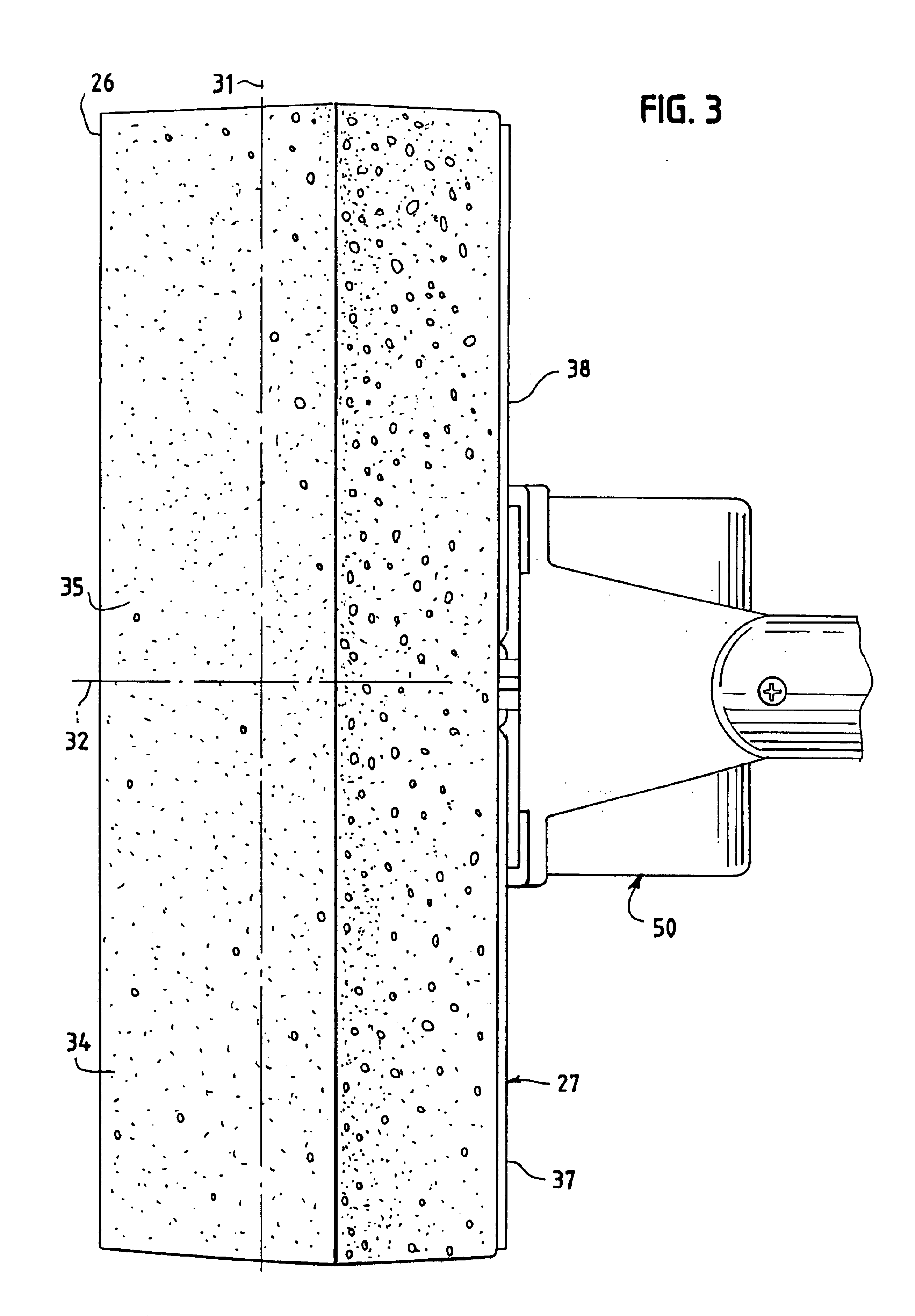
With particular reference to FIGS. 3 and 4, the mop element 26 comprises a flexible, compressible absorbent member which absorbs liquid and from which liquid may be expelled upon compression thereof. The mop element has a longitudinal axis 31 and a central transverse axis 32 generally perpendicular to the longitudinal axis 31. The central axis 32 divides the mop element generally into two regions, a first region 34 and a second r...


PUM


Abstract

Disclosed is a butterfly mop having an elongate shaft with a channel body disposed at one end of the shaft, the channel body having first and second leg portions defining a channel therebetween, the mop further having a mop element including a foldable, compressible, liquid-absorbent member. The mop element and channel body are hingedly movable along a hinge line relative to one another, whereby the mop element may be drawn into the channel causing the mop element to fold along a transverse axis and to become compressed between the channel body leg portions. A manual actuation mechanism includes a handle and a tension rod connecting the handle to one of the mop element and channel body for effecting relative hinged movement thereof. The mop element preferably includes plural pairs of apertures for allowing mounting of the mop element to variously sized mop element supports.

Description

TECHNICAL FIELD OF THE INVENTIONThe present invention is directed toward mops, and more specifically, is in the field of butterfly mops.BACKGROUND OF THE INVENTIONA butterfly mop is characterized in that it comprises an elongate, foldable, compressible, liquid-absorbent member, such as a sponge, which is disposed at one end of a mop shaft, and which is used to absorb liquid, typically water, from a surface. When it is desired to expel liquid from the absorbent member, portions of the absorbent member are folded over one another along a transverse axis of the absorbent member and are compressed, using a folding mechanism such as a roller or track. Butterfly mops are so named because the folding and unfolding of the absorbent member along its transverse axis is said to resemble the motion of the wings of a butterfly.One typical butterfly mop is shown in U.S. Pat. No. 2,892,201. As shown therein, the butterfly mop includes an elongate liquid absorbent member, a plate connected to a sur...

Claims


Application Information

Patent Timeline
Patent Type & Authority Patents(United States)
IPC IPC(8): A47L13/10A47L13/20A47L13/258A47L13/146
CPCA47L13/258A47L13/146
Inventor SPECHT, PAUL B.WAGNER, EDGAR
Owner FREUDENBERG HOUSEHOLD PROD LP
Why Eureka
Try Eureka